


Electrical Planning Notes:
Reference below, for schematic wiring diagram example. Use electrical components as described, including
electrical connectors that are appropriate for the operating environment of the fuel system, whether its use in street,
racing, or marine applications. Pump's Electrical Connector is compatible with Delphi Weather Pack®; two pin
female connectors (such as P/N 12015792), that is included. All electrical connectors for the power leads must be
capable of high current draw, note all connections, wire and component rating requirements herein. Solder can be
used if crimp connections are not reliable, and use shrink wrap for wire splices for extra reliability. Use of a check
valve in fuel system as shown in plumbing diagram will maintain fuel pressure at normal levels during engine
starting and may be required depending on the wiring of main relay control circuit. OEM and some aftermarket
ECMs have fuel pump relay control outputs can be used that will turn off fuel pump during engine starting, requiring
check valve use. If the fuel pressure does not maintain during engine starting,
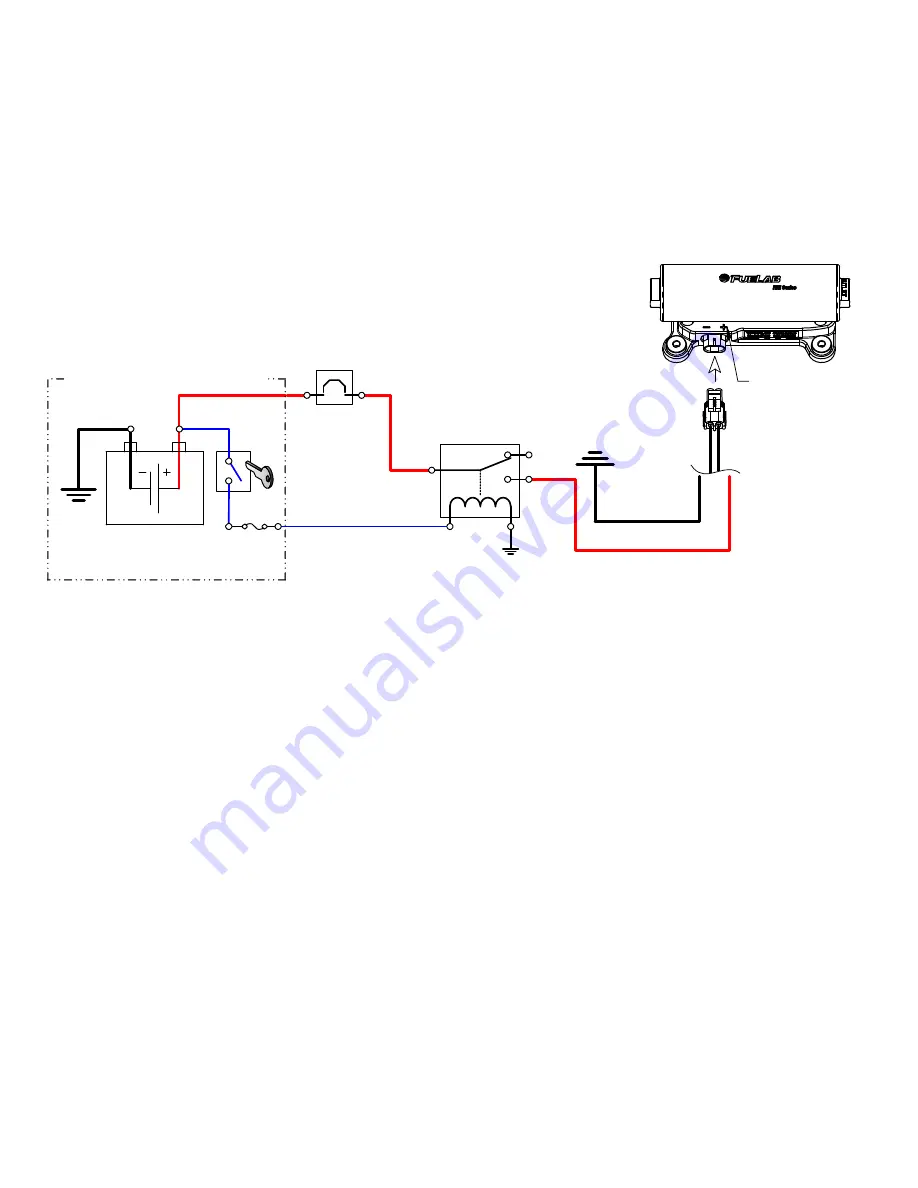
ensure fuel pump is energized while starting. Main wiring schematic diagram,
below shows the control of relay by ignition switch. This source can be changed
as described, or by a toggle switch. Some forms of racing have specific rules
regarding electrical switching of fuel pump, including protective measures such as
oil pressure switches that turn off pump in case engine stops running, as a safety
feature. Consult appropriate racing guidelines, rules and regulations.
Installation Steps:
1. Disconnect the ground terminal from battery and allow the vehicle’s engine and exhaust system to cool.
Relieve fuel system pressure per applicable service manual. Follow all Warnings, Cautions and Instructions
written on previous pages of these instructions.
2. Modify, remove or replace other fuel system components as required per established build plan (reference
notes on previous pages and above).
3. Choose a location for the fuel pump that minimizes exposure to road hazards and debris, away from engine
exhaust pipes, near fuel tank or cell (keep pump as low as possible to help "draw" fuel in). Note position and
plumbing requirements as stated earlier in these instructions. All plumbing must be in accordance to
instructions herein, particularly with all upstream plumbing (between fuel tank and fuel pump)! Excessive
restrictions upstream of the fuel pump will permanently damage the fuel pump. Fuel pump has an incorporated
mounting bracket with shock dampeners. Use the pump as a template to aid in determining location for
mounting hardware (1/4" hardened fasteners are recommended).
4. Install the fuel fittings (not supplied). The threads used on these
Fuel Ports
are not tapered or pipe threads.
Do not use Teflon
®
thread tape or thread sealant on these threads, as this can cause leakage or introduce
debris into the fuel system. Fittings to be used with these style of ports require use of the enclosed -910
O-
rings
for proper sealing. Use light oil to lubricate the
O-rings
just prior to installation. Install the
O-rings
onto
the fuel fitting first. Position the
O-ring
in the thread relief of the fitting. Thread fitting into fuel pump and tighten
between 5 and 15 ft·lbs of torque.
5. Inspect fuel system for any contact of fuel lines or wires with other components that can cause chafing or
rubbing. Secure all components and fuel lines. Ensure that moving components of vehicle are clear.
6. Connect the vehicle’s battery. Perform initial priming: The Fuel Pump may require priming during initial
operation and for moment after depletion of fuel from fuel tank or cell. This action can be accomplished by
removing fuel line from fuel rail (downstream of fuel pump and filters), allowing the fuel line to empty fluid into
fuel safe container. Operate fuel pump until fuel exits fuel line. Attach fuel line back to the fuel rail after priming
fuel pump. After tightening connection, verify leak-free operation while checking fuel rail pressure. If fuel
pressure is not high enough, repeat priming procedure to ensure that fuel pump is receiving fuel from tank.
Turn on fuel pump (typically by bypassing fuel pump relay) without engine operating. ECU or engine
management computer may be controlling the relay. The ECU may only operate pump for a few seconds each
time ignition switch is set to on. The pump will have to operate several seconds (30+) to prime and drive air out
NOTE POLARITY!
Reverse Polarity
Will Damage
Pump!
110020726-1, No Rev Page 3 of 6
CIRCUIT
BREAKER
or FUSE
(25A-30A)
C
NO
NC
FUEL PUMP
POWER RELAY
(25+A RATING)
(10-12ga)
(10-12ga)
VEHICLE BATTERY
(12-16 Volt System)
VEHICLE ELECTRICAL SYSTEM
IGNITION
SWITCH
or ECM
(10-
12ga)
(16-20ga)
FUSED
CIRCUIT
(1-5A)


