700-SDI-RADAR-300W-Man Rev 2 30 May 2022
21
/39
Part# 21370
Change averaging length:
7+1! - set averaging to 1 sample (minimal value)
7+50!
- set averaging to 50 samples
7+250!
- set averaging to 250 samples
7+512!
- set averaging to 512 samples (maximal value)
Change flow direction filter type:
9+0! - both directions enabled
9+1! - detect only incoming flow
9+2! - detect only outgoing flow
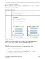
X COMMANDS WHICH USE THE MODBUS REGISTER
There are several X-commands which can be used to read or write values directly from or to the
Modbus register. In order to use these commands, refer to Table 4-5: Retrieving Data from the
Sensor and 4-6: Writing Data to the Sensor to determine the Modbus address of the desired data.
IMPORTANT!
In the following commands the register address, denoted by “d” or
“d1” must be replaced with a numeric value not the hexadecimal value listed in the
“Data Start Addr” column of Tables 4-5 and 4-6.
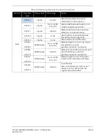
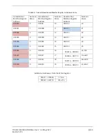
To convert the hexadecimal value to the numeric value refer to Table 4-8 :
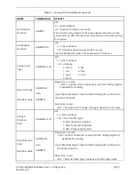
DEFINITION
X COMMAND
RESPONSE AND DETAILS
Read Modbus
holding register
d!
Response: a<val0>
val0 = number of seconds to wait until the holding register is
available for reading
+d = register address
Read Modbus
input register
d!
Response: a<val0>
val0 = number of seconds to wait until the input register is
available for reading
+d = register address
Read last value
aXGRMV!
Response: a<val0>
val0 = the last received Modbus value requested by
d! or d!
Write Modbus
holding register
d1+d2!
Response: a<val0>
val0 = written value
+d1 = holding register address
+d2 = value

