background image

Page | 3  


Installation Introduction 

I. Working with Quick Connect Fittings 

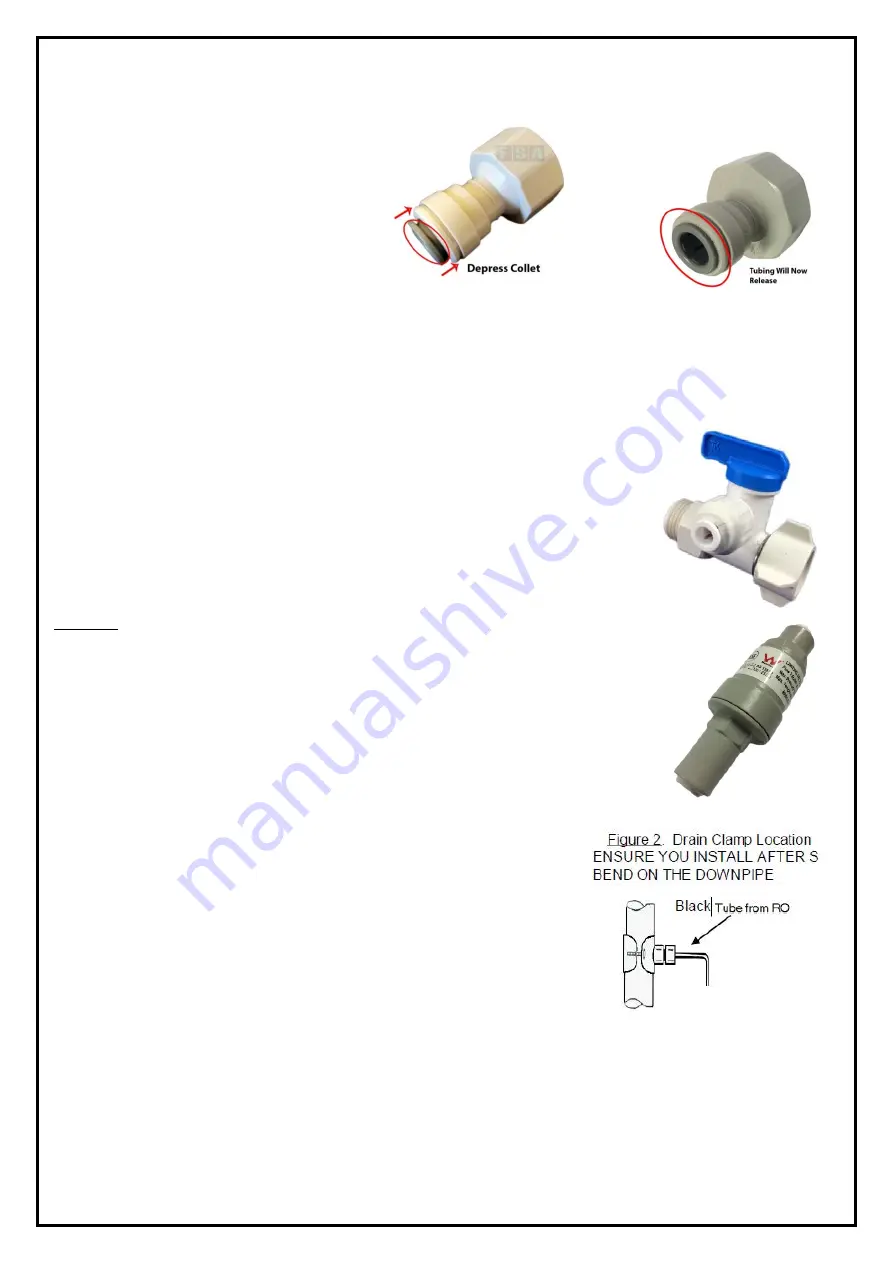
If you come across a push-fit fitting, you 
need to firmly push the tubing into the 
opening until you feel a “click” which 
signifies that the tubing has pushed 
through the internal O-ring and is seated 
correctly. If leaking occurs, it may be due 
to roughly cut tubing OR the tubing is not 
pushed in far enough. To remove tubing 
from push-fit fittings, depress the floating 
collet (shown to the right), then pull the tubing out. 

II. Flushing 

Laws and regulations prevent us from wet-testing these filtration systems prior to sending them out. 
Therefore, during assembly of these systems they are not pressure tested so it is possible to have a small 
leak in a connection (which is simply fixed by re-seating the tubing or tightening a fitting). As the filters are 
dry packed, the systems will require flushing before first use. 

Installing Connections 

I. Feed Water Connection 

Using the supplied Feed Water Adaptor [FWA] (Pictured right), Locate the 
connection between the kitchen tap & cold-water line (Usually a flex line). Shut 
off the incoming water and bleed pressure from the line by opening the tap. 
Disconnect the flex line from the cold-water inlet and install the Feed Water 
Adaptor in between. 
DO NOT apply thread tape to these connections as they are designed to use the 
washers only – Thread tape is only required on the male thread of the FWA if it is 
not installing to a flex line.  
With the blue handle facing in line with the cold-water line (As pictured) the valve is 
in the off position. During this point, you can turn the water back on to check for 
leaks in the valve installation. 

A pressure limiting valve must be fitted between the FWA and the Filter System to 
limit the incoming pressure to a maximum of 500 kPa (70 PSI). Failure to install a 
PLV may void warranty.  

II. Drain Clamp 

The best installation point for the drain clamp is below the S bend 
(Trap). The Vertical tailpiece is ideal. 

1.  Mark the position of the hole on the pipe and drill through using 

a ¼” (6mm) drill bit (One side only). 

2.  Unscrew the clamp and wrap it around the pipe, loosely screw 

it back up leaving enough slack so you can position the hole 
with the outlet of the clamp.  

3.  Tighten the clamp to create a seal.  

III. Drilling Faucet Hole - Stainless Steel Sink) 

1.  Drilling through a stainless-steel sink can be achieved by marking the location with a centre punch 

and drilling a 3/16” Pilot Hole – When drilling through stainless steel – lower speeds are better with 
a sharper bit to avoid burning the surface of the sink. 

2.  Using a 1/2” or 7/16” carbide or sharp drill bit, enlarge the hole to fit the stem of the faucet (7/16” 

Thread) 

Содержание GT1-26-5

Страница 1: ...ion 3 II Drain Clamp 3 III Drilling Faucet Hole Stainless Steel Sink 3 IV Mounting the Faucet 4 4 V Storage Tank Assembly 4 VI Assembling the System Photos Below 5 Connecting the RO System 6 I Tubing...

Страница 2: ...sure 350 kPa 700 kPa Temperature 4 5 C 38 C pH Level 2 11 TDS 0 mg L 2 000 mg L Iron 0 mg L 0 3 mg L Manganese 0 mg L 0 1 mg L Hardness 0 mg L 200 mg L III Space Requirements System Dimensions 5 Stage...

Страница 3: ...Water Adaptor in between DO NOT apply thread tape to these connections as they are designed to use the washers only Thread tape is only required on the male thread of the FWA if it is not installing...

Страница 4: ...und a stem gasket to seal the water the compression ring then prevents the tubing from being removed In this instance thread the Compression nut over the tubing followed by the cone washer Then firmly...

Страница 5: ...ternal cartridges maintain minimal contact with the surface of the carbon filter handle by the end caps only to avoid contamination 5 Screw up the housings while they are in a vertical position to ens...

Страница 6: ...eaches the membrane 5 When the water first comes out of the tap it will be grey and discoloured this is normal as the carbon fines are flushed out of the dry filters NOTE Air bubbles are also common i...

Страница 7: ...l tank of water Maintenance I Replacement Parts Filtration tubing should be replaced periodically about every 3 5 years There is no specific time Fittings should be replaced every 3 5 years due to wea...

Страница 8: ...ally this noise is caused when the installer fails to install the membrane into the housing which causes certain parts of the system to malfunction Check the box and packaging for any leftover or spar...

Страница 9: ...our units and conduct research If you feel that there is an issue with your pH please contact us Strange taste to the water New System 1 Alkaline Filter 2 Residue 3 Contamination 1 If you are using an...

Страница 10: ...Check the feed water conditions and replace the filters if they are passed the recommended change times Water constantly running to waste 1 Air Lock 2 Faulty Shut Off Valve 3 Still Filling 4 Low Press...

Страница 11: ...acts as a cushion which compresses when system pressure suddenly increases or surges as a result of hydraulic shock The water hammer arrestor is installed either at your washing machine or your dishwa...

Страница 12: ...stems must be installed by a qualified plumber The consumer is responsible for keeping record and proof of installation in the form of an invoice and or receipt Filter systems must be maintained as pe...

Страница 13: ...to terms and conditions outlined below This extended warranty covers the below parts of the system GT8 0S Twin O Ring Housings GT8 31 Reverse Osmosis Housing GT35 12 NPT Stainless Steel Centre Joiner...

Страница 14: ......

Отзывы: