background image

Data Center, Enterprise & ISP Network Solutions

25

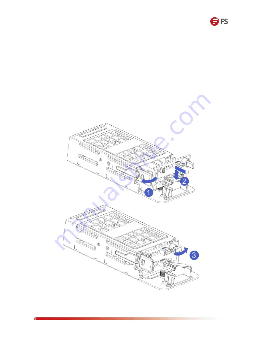
4.9 Rear Hard Disk Module Backplane Installation

Step 1: Rear disk module backplane installation
1-1. Turn the backplane limit spring outwards by hand and press it against your hand - keep the shrapnel
open.
1-2. The hard disk backplane peg holes are aligned with the hard disk module bracket after the pegs are
pushed in. After being lowered into place, the hard disk limit spring is released and the shrapnel springs back
to its original position automatically.
1-3. Flip the fasteners on the backplane of the hard disk, as shown in the figure - the fasteners can be placed
flat.

Содержание RS-7188

Страница 1: ...1...

Страница 2: ...y Installation 15 4 4 Hard Disk Installation 16 4 5 Front Hard Disk Backplane Installation 18 4 6 M 2 SSD Installation 19 4 7 PCIe Module Installation 21 4 8 Rear Hard Disk Module Installation 23 4 9...

Страница 3: ...analysis cloud computing virtualization and greatly improves the resource utilization in data centers The architecture of the platform is based on modular design for flexible configuration and mainten...

Страница 4: ...data throughput with up to 8x PCI expansion slots including 1x non standard PCIe x8 SAS RAID mezzanine card 1x non standard PCIe x8 NIC mezzanine card Flexible Storage Design Front Bays up to 12x hot...

Страница 5: ...to 25x hot swap 2 5 SAS SATA HDD SSD Rear up to 6x hot swap 2 5 SAS SATA HDD SSD Or up to 4x hot swap 3 5 2x 2 5 SAS SATA HDD SSD NVMe up to 16 hot swap 2 5 NVMe SAS SATA HDD SSD Chipset Intel PCH se...

Страница 6: ...g an external USB device make sure that the USB device is in good condition Otherwise the server may work abnormally LCD dedicated interface Mini USB Used to connect an external LCD module It is mainl...

Страница 7: ...t located UID button description Short press this button to turn the positioning light on off System fault indicator Off The device is operating normally Blinking yellow It indicates that the device i...

Страница 8: ...erface USB interface USB 3 0 2 Provides an out of port USB interface through which USB devices can be accessed NOTE When using an external USB device make sure that the USB device is in good condition...

Страница 9: ...UID indicator The UID indicator is used to conveniently locate the server to be operated It can be turned off or turned on by pressing the UID button or the iBMC command remotely Blue solid blinking I...

Страница 10: ...710L BM1 X710L BM2 One PCIe PORT X4 LANE to PCIe M 2 SLOT leads out from the CPU 1 on the mainboard and supports PCIe M 2 storage media Two Gigabit BASE Ts are integrated on the main board and Intel I...

Страница 11: ...P 13 RISER1 PCIe3 0X24 14 RS232 15 M 2 CONN 16 RISER2 PCIe3 0X24 17 VGA 18 NMI BUTTON 19 DEDICATED LAN 20 USB2 21 USB1 22 Ethernet 2 23 Ethernet 1 24 ID BUTTON 25 RISER3 PCIe3 0X16 26 HDD PWR2 27 SATA...

Страница 12: ...ation 1 SAS SATA hard disk connector 1 Maximum support 12G b SAS hard drive 2 Maximum support 6G b SATA hard disk 3 Support SAS SATA hard disk hot swap J5 J6 J7 J8 J9 J10 J11 J12 J13 J14 J15 J16 Botto...

Страница 13: ...hard disk indicator J18 3 5 DIMM Slot Location The server supports Intel Xeon Scalable processors and provides 24 DDR4 DIMM slots 1866 2133 2400 2666MHz The location of slots as shown below 3 6 Hard...

Страница 14: ...1 PCIeX16 When the 3 5 hard disk module is connected the Slot 4 to the Slot 6 cannot receive any other extensions Module When connected to a 2 5 hard disk module Slot 4 to Slot 5 are occupied and can...

Страница 15: ...end of the holding plate 1 2 Press the other end of the holding tab in the direction of the arrow to secure the CPU to the holding tab Step 2 Install the CPU on the heat sink to ensure that the surfa...

Страница 16: ...plate shown below 2 Align the heat sink with the heat sink retention studs on the CPU base and tighten the heat sink retention screws as indicated As shown below Note The pins on the motherboard are e...

Страница 17: ...mainboard CPU 1 are DIMMA1 A2 DIMMB1 B2 DIMM C1 C2 and DIMMs D1 D2 the eight memory slots controlled by the CPU 2 are DIMME1 E2 DIMMF1 F2 DIMMG1 G2 and DIMMH1 H2 should pay attention to the memory of...

Страница 18: ...rd Disk Installation Installing a 3 5 inch hard disk 1 1 Put the hard disk in the tray 1 2 There are 4 countersunk screws on the left and right sides to lock the hard disk the screw head must not prot...

Страница 19: ...Enterprise ISP Network Solutions 17 Installing a 2 5 inch hard disk 1 1 Put the hard disk in the tray 2 2 The bottom four countersunk screws lock the hard disk screw head protrudes from the underside...

Страница 20: ...on in Place 4 5 Front Hard Disk Backplane Installation Front hard disk backplane installation 1 1 The goggle holes and hanging holes on the left and right sides of the hard disk backplane are aligned...

Страница 21: ...Data Center Enterprise ISP Network Solutions 19 4 6 M 2 SSD Installation Step 1 Install the positioning studs according to the length of the M 2 card to be installed...

Страница 22: ...utions 20 Step 2 Install the M 2 Card 2 1 Insert the M 2 card connector end into the motherboard connector as shown 2 2 Press the other end of the M 2 card to the positioning stud plane in step 1 Step...

Страница 23: ...ork Solutions 21 4 7 PCIe Module Installation Steps Rear window PCIe assembly placed vertically downwards aligned with the PCIe slot aligned with the locating hole placed flush with the rear window I...

Страница 24: ...Data Center Enterprise ISP Network Solutions 22 I O module 2 installation method...

Страница 25: ...ons 23 4 8 Rear Hard Disk Module Installation Rear HDD tray installation Step 1 HDD tray is placed vertically and flush with the rear window Step 2 Post fixed HDD tray assembly 2 1 Lock two countersun...

Страница 26: ...twork Solutions 24 I O Module 1 2 5 inch HDD tray Rear Installation 1 1 Place it vertically downwards and align it with the lower guide pin 1 2 After flattening push it in the direction of the arrow 1...

Страница 27: ...t against your hand keep the shrapnel open 1 2 The hard disk backplane peg holes are aligned with the hard disk module bracket after the pegs are pushed in After being lowered into place the hard disk...

Страница 28: ...rk card has a dedicated blank for installation Step 1 Install the back end expansion network card 1 1 Schematically obliquely downwards 1 2 Align the expansion card window and push it in the direction...

Страница 29: ...he back end expansion network card 2 1 Turn the insulation pad up and down in the direction of the arrow to leak out the screw holes 2 2 Locking 3 Flathead Screws 2 3 After the screws are locked reset...

Страница 30: ...Enterprise ISP Network Solutions 28 4 11 Power Module Installation Step The power supply is pushed in the direction of the arrow and the shrapnel wrench on the right emits a sound indicating that it...

Страница 31: ...rk Solutions 29 4 12 PCIe Expansion Card Installation Step Install the PCIe card 1 1 Load the PCIe card in the direction indicated in the figure 1 2 Rotate the PCIe card lock 1 3 Lock the PCIe card lo...

Страница 32: ...he fan module vertically downwards by pressing the arrow Caution that the fan module faces 4 14 Windshield Installation Step The wind shield module is aligned with the hanging points on the left and r...

Страница 33: ...n Step Install the optical drive 1 1 Install the optical drive fasteners in the direction of the arrow and tighten the pan head screws 1 2 Align the opening of the optical drive on the chassis and pus...

Страница 34: ...p 1 Install the front cover of the chassis 1 1 Top Peg Placement Aligns the open position of the cabinet and places it downwards 1 2 Push in the direction of the arrow until the front cover is flush w...

Страница 35: ...twork Solutions 33 Step 2 After installing the chassis cover 2 1 Top cover pegs are aligned with the opening of the cabinet and are placed downward 2 2 Rotate the upper cover lock in the direction of...

Страница 36: ...Pull out the inner rail from the guide rail and you can hear a click and stop 1 2 Push the white button in the direction of the arrow while pulling out the inner rail completely outwards 1 3 Complete...

Страница 37: ...with the four hanging screws on the side of the chassis and install the inner rail to the chassis according to the diagram After the installation is completed you can hear a click and need to be insta...

Страница 38: ...d install the guide rail into the cabinet 3 2 After installing the rail into the cabinet rear end you can hear the click sound and complete the installation of the rear rail 3 3 Push the front end of...

Страница 39: ...he arrow to ensure that the inner rails fit smoothly into the center rail 4 3 After pushing the server into the middle track you can hear a click and stop 4 4 Push the blue button in the direction of...

Страница 40: ...ion 6 1 1 Enter BIOS Setup Interface Steps 1 Power on the server board and connect the keyboard 2 During the POST process observe the prompt at the bottom left of the Logo screen and enter the BIOS Se...

Страница 41: ...k the motherboard specification and confirming that the motherboard supports IPMI then finding the dedicated IPMI port on the motherboard or to select the shared Ethernet port as shown in Figure 2 2 F...

Страница 42: ...ress ESC or DEL while the device is starting to enter the BIOS interface as shown in Figure 2 4 Figure 2 4 BIOS Setting Interface After entering the interface use the left and right keys of the keyboa...

Страница 43: ...ce On this page there are two channels to configure the one of channels is the Dedicated private port and another one is the shared port for Sharelink Take the shared port for example If you connect a...

Страница 44: ...IP addresses between the devices cannot be duplicated Otherwise communication cannot be established 2 If the IP of your IPMI device is an intranet address the terminal device that communicates with it...

Страница 45: ...og in to the IPMI management interface The IPMI management interface can be accessed using a standard web browser Here we recommend Google Chrome browser Firefox browser and IE browser IE 11 or above...

Страница 46: ...Data Center Enterprise ISP Network Solutions 44 In this page click Advanced Continue to to access the IPMI management page normally and enter the login page as shown in Figure 3 1...

Страница 47: ...Data Center Enterprise ISP Network Solutions 45...

Отзывы: