9
EN
Further explanati-
ons regarding the
“Gasflow regula-
tor with flow-rate
indicator”
(continued)
3.
Press the “Process” button to select the “4-step mode”
4.
Press the gas-test button on the power source, or the torch trigger
5.
Carefully open the pressure regulator on the gas cylinder until the maximum value
of 30 SL/min is shown on the flow-rate indicator
6.
Press the gas-test button on the power source, or the torch trigger
7.
Close the gasflow regulator
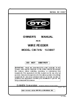
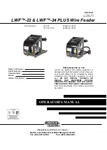
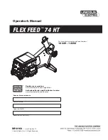
Side of wirefee-
der
Rear of wirefee-
der
(2)
(1)
(3)
Item Function
(1)
(+) socket with bayonet latch
for MMA (manual electrode) welding
(2)
(+) socket with bayonet latch
interconnecting cable
(3)
LocalNet connection socket
interconnecting cable
(4)
Screw-type connection for water
return flow (red)
interconnecting cable
(5)
Screw-type connection for water
forward flow (blue)
interconnecting cable
(6)
Shielding gas connection socket
(6)
(5)
(4)
Fig.7
VVR 2000 - rear view
(2)
(1)
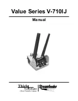
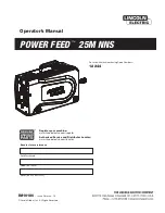
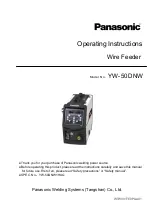
Fig.8
VR 2000 - side view
(3)
Item Function
(1)
Wirespool holder with braking device
for holding standardized 200 mm (7,87 in) welding-wire spools weighing up to 5 kg
(11,02 lbs.)
(2)
2-roller drive
(3)
Mode selector switch option