


Section 4 Component Teardown
4-10
Control Panel Assembly And Control Unit
Removal
1. Disconnect the power supply cord.
2. Open the door and block it open.
3. Remove one (1) screw holding the hood exhaust lou-
ver to oven cavity front flange.
4. Remove the hood exhaust louver from the oven by
pushing the right and left tabs of the hood exhaust
louver. (Refer to procedure of “HOOD EXHAUST
LOUVER REMOVAL”)
5. Remove one (1) screw holding the control panel to
the oven cavity front face plate.
6. Release the control panel from the oven cavity front
face plate by lifting it up.
7. Disconnect the wire leads from the relays RY1 and
RY2.
8. Disconnect the connectors CN-A, CN-B, CN-C, CN-E
and CN-F from the control unit.
9. Remove the control panel assembly from the oven.
10. Now, the control panel assembly is free.
11. Disconnect the ribbon cable from the connector
CN-G.
12. Remove three (3) screws holding the control unit to
the key fixing plate.
13. Now, the control unit is free.
Graphic Sheet And Membrane Switch
Replacement
REMOVAL
1. Disconnect the power supply cord and then remove
outer case.
2. Open the door and block it open.
3. Discharge high voltage capacitor.
4. Remove the control panel assembly, referring
to chapter of CONTROL PANEL ASSEMBLY AND
CONTROL UNIT REMOVAL.
5. Disconnect the ribbon cable from the connector
CN-G.
6. Tear away the graphic sheet from the control panel
frame.
7. Tear away the membrane switch from the control
panel frame.
REINSTALLATION
1. Remove remaining adhesive on the control panel
frame surfaces with a soft cloth soaked in alcohol.
2. Tear the backing paper from the new membrane
switch.
3. Insert the ribbon cable of the membrane switch into
the slit of the control panel frame and key fixing
frame.
4. Adjust the upper edge and right edge of the
membrane switch to the small depression on the
surface of the control panel frame.
5. Attach the membrane switch to the control panel
frame by rubbing with a soft cloth not to scratch.
6. Tear the backing paper from the new graphic sheet.
7. Adjust the upper edge and right edge of the graphic
sheet to the large depression on the surface of the
control panel frame.
8. Attach the graphic sheet to the control panel frame
by rubbing with a soft cloth not to scratch.
9. Reconnect the ribbon cable to the connector CN-G.
10. Reconnect all leads and connectors removed from
the control unit
11. Reinstall the control panel assembly to the oven
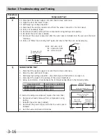
Key Fixing Frame
S lit
Control P anel
Ribbon Cable
Key sheet (Graphic sheet)
F P C (Membrane switch)
Control Unit
Figure 4-7. Key Unit Location
To discharge the high voltage capacitor, wait for 60
seconds and then short-circuit the connection of the
high-voltage capacitor (that is the connecting lead of
the high-voltage rectifier) against the chassis with the
use of an insulated screwdriver.
NOTE
Содержание CGMV173KB
Страница 2: ......
Страница 14: ...Section 2 Operation 2 2 Figure 2 1 Oven Off Condition Figure 2 2 Oven ON Cooking Condition ...
Страница 51: ...Section 5 Wiring Diagrams 5 1 Wiring Schematic Oven ON Condition ...
Страница 52: ...Section 5 Wiring Diagrams 5 2 Pictorial Component Diagram ...
Страница 54: ...Section 5 Wiring Diagrams 5 4 LD1 LD2 LD3 LD4 LD5 Control Board ...