background image

PAEC3200C

4

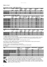
Output charts water PAEC3200CW

*

1

) Recommended outlet air temperature for good comfort and optimized output. 

*

2

) Nominal output at given supply and return water temperature. 

Supply water temperature:80 °C


Room temperature: +18 °C


Outlet air temperature: +35 °C*

1

Water temperature: 80/60 °C


Room temperature: +18 °C


Type

Fan 


position

Airflow


[m

3

/h]

Output  


[kW]

Return 

water 

temp. 

[°C]

Water 


flow


[l/s]

Pressure 

drop


[kPa]

Output*

2


[kW]

Outlet


air temp.


[°C]

Water


flow


[l/s]

Pressure 

drop


[kPa]

PAEC3210CW-NA

max

1460

10.0

42

0.06

1.4

14.9

42

0.18

8.8

PAEC3215CW-NA

max

2150

15.3

38

0.09

2.0

24.2

45

0.30

16.2

PAEC3220CW-NA

max

2920

21.2

38

0.12

2.6

33.4

44

0.41

21.6

Supply water temperature: 60 °C


Room temperature: +18 °C


Outlet air temperature: +35 °C*

1

Water temperature: 60/40 °C


Room temperature: +18 °C


Type

Fan 


position

Airflow


[m

3

/h]

Output  


[kW]

Return 

water 

temp. 

[°C]

Water 


flow


[l/s]

Pressure 

drop


[kPa]

Output*

2


[kW]

Outlet


air temp.


[°C]

Water


flow


[l/s]

Pressure 

drop


[kPa]

PAEC3210CW-NA

max

1460

10.2

48

0.20

10.9

8.2

32

0.10

3.2

PAEC3215CW-NA

max

2150

14.6

42

0.20

8.7

13.6

33

0.17

6.1

PAEC3220CW-NA

max

2920

21.6

45

0.35

17.2

18.9

33

0.23

8.1

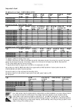
Metric chart

Imperial chart

*

1

) Recommended outlet air temperature for good comfort and optimized output. 

*

2

) Nominal output at given supply and return water temperature. 

Supply water temperature:176 °F


Room temperature: +64 °F


Outlet air temperature: +95 °F*

1

Water temperature: 176/140 °F


Room temperature: +64 °F


Type

Fan 


position

Airflow


[cfm]

Output  


[MBH]

Return 

water 

temp. 

[°F]

Water 


flow


[US gal/h]

Pressure 

drop


[kPa]

Output*

2


[MBH]

Outlet


air 

temp. 

[°F]

Water 


flow


[US gal/h]

Pressure 

drop


[kPa]

PAEC3210CW-NA

max

1050

34.1

108

61.3

1.4

50.9

108

173.1

8.8

PAEC3215CW-NA

max

1550

52.2

100

84.6

2.0

82.6

113

280.6

16.2

PAEC3220CW-NA

max

2150

72.4

100

117.9

2.6

114.0

111

388.1

21.6

Supply water temperature: 140 °F


Room temperature: +64 °F


Outlet air temperature: +95 °F*

1

Water temperature: 140/104 °F


Room temperature: +64 °F


Type

Fan 


position

Airflow


[cfm]

Output  


[MBH]

Return      

water 

temp. 

[°F]

Water 


flow


[US gal/h]

Pressure 

drop


[kPa]

Output*

2


[MBH]

Outlet


air 

temp. 

[°F]

Water 


flow


[US gal/h]

Pressure 

drop


[kPa]

PAEC3210CW-NA

max

1050

34.8

118

188.3

10.9

28.0

90

94.0

3.2

PAEC3215CW-NA

max

1550

49.8

108

193.1

8.7

46.4

91

156.9

6.1

PAEC3220CW-NA

max

2150

73.7

113

331.9

17.2

64.5

91

217.8

8.1

Содержание PAEC3200C Series

Страница 1: ...A Seal The ratings shown are based on tests and procedures performed in accordance with AMCA Publication 211 and AMCA Publication 311 and comply with the requirements of the AMCA Certified Ratings Program The AMCA Certified Ratings Seal applies to airflow rate average outlet velocity outlet velocity uniformity velocity projection and power rating at free delivery only ...

Страница 2: ...3500 75 39 270 1 7 208V3 36 51 PAEC3210CE 480 NA 4 8 1750 73 11 135 0 9 480V3 10 26 PAEC3215CE 480 NA 6 12 2450 72 16 147 0 9 480V3 15 37 PAEC3220CE 480 NA 8 16 3500 75 21 270 1 7 480V3 20 51 PAEC3210CE 600 NA 4 8 1750 73 9 135 0 9 600V3 8 26 PAEC3215CE 600 NA 6 12 2450 72 13 147 0 9 600V3 12 37 PAEC3220CE 600 NA 8 16 3500 75 17 270 1 7 600V3 16 51 Type Output kW Airflow 1 m3 h Sound power 2 dB A ...

Страница 3: ...w of totally 3 fan steps 2 Values shown are for total sound power levels for Installation Type A free inlet free outlet The Sound power level ratings shown are in decibels referred to 10 12 watts calculated per AMCA Standard 301 3 FLA total amperage for motor and heat 4 Applicable at water temperature 140 104F air temperature in 64F Above table is valid for 208V 1ph 60Hz Also approved for 230V 1ph...

Страница 4: ... 0 20 8 7 13 6 33 0 17 6 1 PAEC3220CW NA max 2920 21 6 45 0 35 17 2 18 9 33 0 23 8 1 Metric chart Imperial chart 1 Recommended outlet air temperature for good comfort and optimized output 2 Nominal output at given supply and return water temperature Supply water temperature 176 F Room temperature 64 F Outlet air temperature 95 F 1 Water temperature 176 140 F Room temperature 64 F Type Fan position...

Страница 5: ...f pictures For translation of the English texts used see the respective language pages EN Les pages de présentation contiennent principalement des images Pour la traduction des textes en anglais consultez la page correspondante à la langue souhaitée FR ...

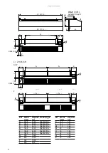
Страница 6: ...0 458 167 min 500 99 209 50 52 DN20 3 4 167 min 500 min 500 165 209 50 min 500 min 500 167 165 119 DN20 3 4 E C A G G L L M K K N R H Q I P J J O O K G G G F D B DN20 3 4 outside thread L 2 m 6 6 ft A W E Ref Metric mm Imperial in Product type A 2068 81 40 PAEC3220Cx B 2045 80 50 PAEC3220Cx C 1578 62 10 PAEC3215Cx D 1555 61 20 PAEC3215Cx E 1068 42 00 PAEC3210Cx F 1045 41 10 PAEC3210Cx G 500 19 68 ...

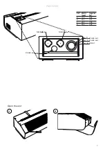
Страница 7: ...PAEC3200C 7 A B Gland Knock out Knock out Knock out ø17 5 ø17 5 ø32 5 ø25 5 ø20 5 ø17 5 Gland Gland Open the unit Ref Metric mm Imperial in A 17 5 0 69 B 20 5 0 81 C 25 5 1 00 D 32 5 1 28 A A A B C D ...

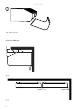
Страница 8: ...PAEC3200C 8 Fig 3 Open the unit C Fig 4 Fig 5 Minimum distance 30 mm 60 mm min 60 30 mm 1 18 in 60 mm 2 36 in min 60 mm 2 36 in ...

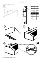
Страница 9: ...with wall brackets PAEC3210Cx 2 pcs PAEC3215Cx 2 pcs PAEC3220Cx 3 pcs A B C D Ø8 3x Ø7 Ø16 213 37 260 75 35 20 Ref Metric mm Imperial in A 260 10 24 B 37 1 46 C 213 8 39 D 75 2 95 E 35 1 38 F 20 0 79 G 8 0 31 H 7 0 28 I 16 0 63 min 500 mm 19 7 in A G x3 H I B C D E F ...

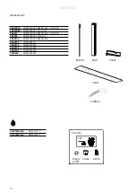
Страница 10: ...A2P15 PAEC3210Cx PAEC3215Cx 1 m 3 3 ft PA2P20 PAEC3220Cx 1 m 3 3 ft PA3PF15 PAEC3210Cx PAEC3215Cx PA3PF20 PAEC3220Cx PA3EF10 PAEC3210CW PA3EF15 PAEC3215CW PA3EF20 PAEC3220CW FHDN20 PAEC3200CW PA34TR PA2P PA3PF FHDN20 PA3EF VLSP15NF NA DN15 1 2 VLSP20NF NA DN20 3 4 VKF SD230 BPV10 VLSP NA Nipple G NPT ...

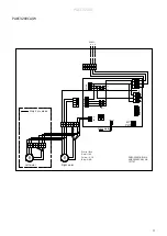
Страница 11: ...5 4 2 3 1 A L PE N SENSOR 208V1 0 10V Only water N L PE L1 L2 L3 N L PE L1 L2 L3 Blue Yellow Red White M M Left motor Right motor 6 5 4 2 3 1 A L PE N Red 10 V Yellow 0 10 Blue GND White Tach 0 10V DOOR AFTER WATER 5A 16A AREC3200CA W NA 157707 PAEC3200CA W NA L1 L2 PE Only 2 m version ...

Страница 12: ... b1 L3 L2 L1 a1 a2 b2 c2 c1 b1 C Over heat cut out L1 L2 L3 L3 L1 L2 C3 L1 L2 L3 L3 L1 L2 C4 L3 L2 L1 a1 a2 b2 c2 c1 b1 L3 L2 L1 a1 a2 b2 c2 c1 b1 208V3 0 10V 6 5 4 2 3 1 A L PE N M M Left motor Right motor 6 5 4 2 3 1 A L PE N Blue Yellow Red White Red 10 V Yellow 0 10 Blue GND White Tach Only 2 m version 5A x 3 5A 16A on off SENSOR AREC3200CE NA 157708 PAEC3200CE NA PE L1 L2 L3 ...

Страница 13: ...FTE R WATER PE N L PE C1 L1 L2 L3 C2 C Over he at cut out L1 L2 L3 C3 L1 L2 L3 C4 0 10V PE L1 L2 L3 6 5 4 2 3 1 A L PE N M M Left motor Right motor 6 5 4 2 3 1 A L PE N Blue Yellow Red White Red 10 V Yellow 0 10 Blue GND W hite Tach Only 2 m version 5A x 3 5A 16A on off S E NSO R 600V3 480V3 2 x 10A FUSE AREC3200CE NA 215224 PAEC3200CE NA ...

Страница 14: ...u d en effectuer l entretien L installation ou l entretien de l unité doivent être effectués par un technicien qualifié seulement L unité ne doit pas être installée et utilisée à l extérieur ou dans un environnement hostile ou potentiellement explosif Au site d installation veuillez vous assurer que le milieu environnant n exige pas une classification IP de l équipement supérieure à ce qui est ind...

Страница 15: ...n the air curtain Unit without heating or with water heating Connected via the built in control board with 1 5 m 4 9 ft cord Unit with electrical heating The electrical connection is made on the top of the unit See Fig 2 208V3 480V3 600V3 power supply for heat and control 1 2 should be connected to a terminal block in the primary terminal box 1 480V3 600V3 Control supply is transformed via interna...

Страница 16: ...ating coil must not be connected to a mains pressure water system or an open water system Note that the unit shall be preceded by a regulating valve see Frico valve kit The water coil is connected on top of the unit via steel pipes with DN20 3 4 terminals external thread Flexible hoses are available as accessories see accessories pages The connections to the heating coil must be equipped with shut...

Страница 17: ... the unit and lift out 6 Install the new coil in reverse order to the above Replacing motor or impeller 1 Remove the front 2 Remove gable end 3 Remove the screw between motor and fan 4 Disconnect the cables to the motor 5 Remove the screws securing the motor and lift it out together with the impeller 6 Install the new motor and or the new impeller as above in reverse order Troubleshooting If the f...

Страница 18: ...ssible obstructions The unit must not be fully or partially covered as overheating can result in a fire risk Lifting equipment must be used to lift the unit This appliance can be used by children aged from 8 years and above and persons with reduced physical sensory or mental capabilities or lack of experience and knowledge if they have been given supervision or instruction concerning use of the ap...

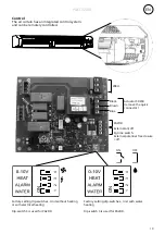
Страница 19: ...Actuator SD230 remove the quick connector Black Brown Blue External on off Eg time switch External potential free closure off Factory setting dip switches Unit with water heating Dip switch 3 is used for PA2DR 2 1 3 Factory setting dip switches Unit without heating or with electrical heating Dip switch 3 is used for PA2DR 208V PA2DR ...

Страница 20: ...tes to vent out the heat if the temperature rises above 50 C again during the following 5 minutes overheating alarm is deployed The red LEDs flash and all the buttons are locked 1 Disconnect the power supply with the isolator switch 2 Determine the cause of overheating and rectify the fault 3 Reconnect the unit Functional test Functional test is started using the remote control Push and in 5 secon...

Страница 21: ......

Страница 22: ......

Страница 23: ...AB Tel 46 31 336 86 00 Industrivägen 41 SE 433 61 Sävedalen mailbox frico se Sweden www frico net For latest updated information and information about your local contact www frico net Art no 159956 KG 17 February 2021 ...

Отзывы: