background image

page 

14

page 

3


»

  Tools  Needed 

WARNING:

FAILURE TO FOLLOW THE ASSEMBLY INSTRUCTIONS IN THIS 

MANUAL CAN RESULT IN PRODUCT DAMAGE, OR PERSONAL INJURY.

1

2

1. Read  instructions 

carefully. Check that 

no parts are missing.

Single Sided 

Wrench

Socket Head

Wrench

Electric Drill

Friant & Associates, LLC does not assume any responsibility for product that is altered in any way.

2. Carefully identify each 

component, especially 

those that are similar. 

The most common 

mistake is mixing 

up the order and 

placement of parts.

Tools Needed


Follow assembly instructions closely


Do not overload the tables (220 lbs maximum straight, 330 lbs maximum 

corner)


The input voltage should be within 108-132V


Use the glides to properly level the table before use


When moving the table, do not tilt the table on one leg or misalignment may 

occur


Before first use, perform reset operation


If, after trouble shooting the problem persists, contact Customer Service for 

further assistance. 

GENERAL TIPS

Содержание FSQAHTB

Страница 1: ...DJUSTABLE TABLE ModelNumber FSQAHTB Please Read Instructions Before Use ASSEMBLY INSTRUCTIONS FRIANT ASSOC 4901 E 12 STREET OAKLAND CA 94601 T 510 535 5113 FAX 510 535 5237 www Friant com systems my hite 081717 ...

Страница 2: ...em 3 Check that the load on the table does not exceed limits 220lbs straight 330lbs corner 4 Table should be level and aligned at all times Thank you for choosing Friant We appreciate the trust and confidence you have placed in us and are committed to providing you the best possible product When placing table in final location be sure there is ample room for adjustment around ALL sides and at the ...

Страница 3: ...ntify each component especially those that are similar The most common mistake is mixing up the order and placement of parts ToolsNeeded Follow assembly instructions closely Do not overload the tables 220 lbs maximum straight 330 lbs maximum corner The input voltage should be within 108 132V Use the glides to properly level the table before use When moving the table do not tilt the table on one le...

Страница 4: ...it exceeded or Other problem 1 Check that weight on table does not exceed limit 2 Perform reset operation if problem persists 3 contact Friant customer service to replace control panel E07 E08 or E09 Signal Interruption Signal is interrupted between leg and computer 1 Perform reset operation if problem persists 2 contact Friant customer service CLEARMAXIMUM MINIMUMHEIGHT 1 Table can be at ANY HEIG...

Страница 5: ... button 2 Press the arrow down V button again and hold til ASR shows on the display 3 Release the button and the ASR will flash on the display 4 Hold the arrow down button again Table will shift up and down slightly as it resets to 24 5 V 1 Press the arrow up button to get to desired maximum height Note the arrow up button must be the last button pressed to set the maximum height You cannot press ...

Страница 6: ...g s repeating steps 3 4 Remove pad when done Make sure the length of the plug in cord is appropriate to both reach the outlet AND for the distance the table will travel up and down Range 24 5 at lowest to 50 highest Step 15 Install the G telescopic cover plates leaving exit space for the electrical power cords and secure to worksurface with M 8 truss head screws M5 20mm Step 16 Turn table right si...

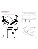
Страница 7: ...ils should be centered between crossbeams Center leg assemblies on the worksurface Make sure your overhang is even on both sides K SOCKET BUTTON HEAD BOLT M6 12mm Base is A 38 68 Maximum recommended top 78 wide Minimum recommended top 40 wide Step 14 Connect E control panel to F control box with H connector wires as shown Use L wire manager to secure H connector wires to underside of worksurface H...

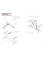
Страница 8: ...mm Step 13 Insert the F control box in between crossbeam Step 12 Secure the E control panel in the desired location with M 2 truss head screws M5 20mm Step 10 Ensure the leg assembly is still centered both side to side and front to back Secure the leg assembly to the worksurface with M 8 truss head screws M5 20mm M TRUSS HEAD SCREWS M5 20mm F CONTROL BOX E CONTROL PANEL ...

Отзывы: