


Vehicle Power Distribution
Electrical power distribution provides battery power to
the electrical and electronic systems.
The following components make up the power distri-
bution system:
•
Battery Cable Access (BCA)
•
Vehicle Power Distribution Module (VPDM)
•
Cab Load Disconnect Switch (CLDS), optional
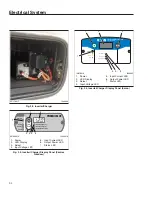
Battery Cable Access (BCA)
The BCA is the primary interface through which bat-
tery power gets transferred from outside the cab to
the inside. It is located on the passenger side of the
engine compartment front wall.
On vehicles equipped with a cab load disconnect
switch (CLDS), the BCA houses a contacting device
that can open to shut off power to high current loads.
On vehicles equipped with an optional high current
receptacle and/or optional inverter, the BCA will have
circuit protection and power cables supplying those
devices.
Vehicle Power Distribution Module
(VPDM)
The VPDM is the primary component for power distri-
bution and circuit protection. The VPDM provides
power for cab and powertrain functions, and various
stand-alone modules, and supplies the emergency
power supply circuits with power in the event of a
module failure. The VPDM is located in the vehicle
electronics bay, behind the passenger-side dash
panel.
Single Signal Detect and Actuation
Module (sSAM)
The single signal detect and actuation module
(sSAM) combines chassis power distribution, cab
power distribution, and modular switch field functions
in a single ECU. The sSAM reads input information
from sensors, switches, and databus messages, and
drives output and CAN messages. The sSAM is lo-
cated behind the lower dash panel.
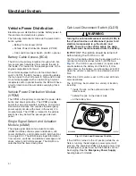
Cab Load Disconnect Switch (CLDS)
WARNING
Turning the cab load disconnect switch (CLDS) to
the off position does not disconnect power to all
electrical components (e.g. the starter and
sSAM). To work on the vehicle safely, the nega-
tive leads must be disconnected from the battery.
IMPORTANT: The ignition should be turned off
before turning the CLDS on or off.
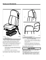
Your New Cascadia vehicle may be equipped with an
optional cab load disconnect switch (CLDS). See
. The CLDS is used to break (or open) select
circuits between the battery and the BCA. It mini-
mizes draw on the battery, and should be set to OFF
when the vehicle is parked for an extended period of
time.
When the CLDS switch is set to ON, a red LED indi-
cator illuminates.
The CLDS may be mounted in a variety of location,
including:
•
inside the cab on the outboard side of the
driver’s seat;
•
behind the cab on the driver’s side;
•
at the battery box.
If the CLDS is turned to the off position while the ve-
hicle is running, the emergency power system will
activate. The powertrain PDM will receive power from
the emergency power feed, but the batteries will not
be charging. See the
Emergency Power Supply
heading below for details.
05/13/2009
f545527
Fig. 9.1, Cab Load Disconnect Switch
Electrical System
9.1
Содержание NEW CASCADIA 2016
Страница 1: ... NEW CASCADIA Driver s Manual Part Number STI 500 Publication Number STI 500 8 ...
Страница 5: ......
Страница 11: ......
Страница 38: ...f611444 10 31 2016 Fig 3 23 Sample Alert Messages Instruments 3 20 ...
Страница 39: ......
Страница 76: ...6 Climate Controls Cab Climate Controls 6 1 Sleeper Climate Control Panel 6 2 Accessory Heaters 6 3 ...
Страница 93: ......
Страница 94: ...8 Cab and Sleeper Features Windows 8 1 Mirrors 8 1 Cab Amenities 8 1 Sleeper Amenities 8 2 ...
Страница 99: ......
Страница 112: ...11 Optional Engine Systems Engine Idle Limiting 11 1 Optimized Idle 11 1 Power Takeoff PTO Governor 11 3 ...
Страница 125: ......
Страница 126: ...13 Brake Systems Air Brake System 13 1 Meritor WABCO Antilock Braking System 13 4 Engine Brake 13 6 ...
Страница 134: ...14 Steering System Power Steering System 14 1 ...
Страница 145: ......
Страница 146: ...16 Manual Transmissions and Clutch Eaton Fuller Manual Transmissions 16 1 Clutch 16 1 ...
Страница 149: ......
Страница 150: ...17 Drive Axles Interaxle Lock Tandem Axles 17 1 Driver Controlled Differential Lock DCDL 17 2 ...
Страница 164: ...19 Trailer Couplings Holland Trailer Coupling 19 1 ...
Страница 166: ...20 Headlight Aiming Headlight Aiming Preliminary Checks 20 1 Headlight Aim Check 20 1 Headlight Aim Adjustment 20 1 ...
Страница 177: ......
Страница 191: ......
Страница 198: ...25 Specifications Fluids and Lubricants 25 1 ...
Страница 200: ...26 Telematics Data Terms of Use 26 1 ...


