


Fast Ethernet Controller (FEC)
MCF52235 ColdFire® Integrated Microcontroller Reference Manual, Rev. 6
18-18
Freescale Semiconductor
discarded until the receive FIFO is serviced by the DMA and space is made available. At this point the
receive frame/status word is written into the FIFO with the OV bit set. This frame must be discarded by
the driver.
18.4.14.2.2
Non-Octet Error (Dribbling Bits)
The Ethernet controller handles up to seven dribbling bits when the receive frame terminates past an
non-octet aligned boundary. Dribbling bits are not used in the CRC calculation. If there is a CRC error,
then the frame non-octet aligned (NO) error is reported in the RxBD. If there is no CRC error, then no error
is reported.
18.4.14.2.3
CRC Error
When a CRC error occurs with no dribble bits, the FEC closes the buffer and sets the CR bit in the RxBD.
CRC checking cannot be disabled, but the CRC error can be ignored if checking is not required.
18.4.14.2.4
Frame Length Violation
When the receive frame length exceeds MAX_FL bytes the BABR interrupt is generated, and the LG bit
in the end of frame RxBD is set. The frame is not truncated unless the frame length exceeds 2047 bytes).
18.4.14.2.5
Truncation
When the receive frame length exceeds 2047 bytes the frame is truncated and the TR bit is set in the receive
BD.
18.5
Programming Model
This section gives an overview of the registers, followed by a description of the buffers.
The FEC is programmed by a combination of control/status registers (CSRs) and buffer descriptors. The
CSRs are used for mode control and to extract global status information. The descriptors are used to pass
data buffers and related buffer information between the hardware and software.
18.5.1
Top Level Module Memory Map
The FEC implementation requires a 1-Kilobyte memory map space. This is divided into 2 sections of 512
bytes each. The first is used for control/status registers. The second contains event/statistic counters held
in the MIB block.
defines the top level memory map.
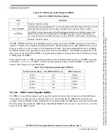
18.5.2
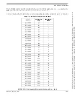
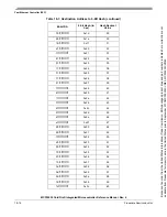
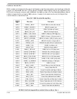
Detailed Memory Map (Control/Status Registers)
shows the FEC register memory map with each register address, name, and a brief description.
Table 18-9. Module Memory Map
Address
Function
0x1000-11FF
Control/Status Registers
0x1200-12FF
MIB Block Counters
Because
of
an
order
from
the
United
States
International
Trade
Commission,
BGA-packaged
product
lines
and
part
numbers
indicated
here
currently
are
not
available
from
Freescale
for
import
or
sale
in
the
United
States
prior
to
September
2010:MCF52234CVM60,
MCF52235CVM60


