


FRDM-KL03Z hardware description
FRDM-KL03Z User’s Guide, Rev. 0
Freescale Semiconductor
7
Freescale Semiconductor
7
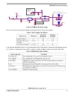
down the RESET push button while plugging the USB cable into USB connector J9. Once the OpenSDA
enters Bootloader mode, other OpenSDA applications such as a debug application can be programmed.
SPI and GPIO signals provide an interface to the SWD debug port of the KL03Z. Additionally, signal
connections are available to implement a UART serial channel. The OpenSDA circuit receives power
when the USB connector J9 is plugged into a USB host.
5.2.1
Debugging interface
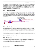
Signals with SPI and GPIO capability are used to connect directly to the SWD of the KL03Z. These signals
are also brought out to a standard 10-pin (0.05”) Cortex Debug connector (J7) as shown in
. It is
possible to isolate the KL03Z MCU from the OpenSDA circuit and use J7 to connect to an off-board MCU.
To accomplish this, cut the trace between pin1 and pin2 of J6 on the bottom layer. This will disconnect the
SWD_CLK pin to the KL03Z so that it will not interfere with the communications to an off-board MCU
connected to J7.
Figure 4. SWD debug connector to KL03Z
5.2.2
Virtual serial port
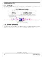
A serial port connection is available between the OpenSDA MCU and LPUART0 pin PTB1(TXD) and
PTB2 (RXD) of KL03Z. Several of the default OpenSDA applications provided by Freescale, including
the MSD Flash Programmer and the P&E Debug Application, provide a USB Communications Device
Class (CDC) interface that bridges serial communications between the USB host and this serial interface
on the KL03Z.
PTB2 is a multiplex pin with VREF_CAP and LPUART0, furthermore PTB2 is configured to manage the
LPUART0_RX function under ROM Bootloader mode. There is one 0.1
F capacitor C35 on the PTB2
pin for VREF stability. We recommend using a maximum baud rate of 38400 bps. If the baud rate
increases, C35 should be removed.
5.3
Clock source
The Kinetis KL03 microcontrollers feature an on-chip oscillator compatible with low ranges of input
crystal or resonator frequencies: 32 KHz to 40 KHz (low frequency mode).
The KL03Z on the FRDM-KL03Z is clocked from a 32,768 Hz crystal.
6:'&211(&725
7KHUHLVDERWWRPOD\HUWUDFH
VKRUWLQJSLQWRSLQRIMXPSHU
$'&B6(&03B,137$,54B//:8B3730B&+6:'B&/.
39B0&8
6:'B',2B7*70&8SJ
6:'B&/.B7*70&8SJ
567B7*70&8SJ
-
'13
-
'13
+'5;7+
+'5;


