3
TEST RUNNING
If test running pump before installation:
1. Ensure that the power supply corresponds with that shown
on the nameplate of the motor.
2. Install pump and components appropriate for the test.
3. Make sure power supply is turned off and circuit breaker
or disconnect switch is open. Make electrical connections
appropriate to your motor as shown in Figure 2.
4. Run pump and motor unit for a few seconds to ensure that it
is in working order.
SUITABILITY OF WATER SOURCE
Water from an undeveloped source often contains an excessive
amount of sand, dirt, and abrasives which can damage the
pump. Make arrangements to ensure an adequate
fl
ow of water
over the motor for cooling purposes. Determine the correct
pump setting by taking into account the static water level and
the drawdown at the proposed pumping rate.
DROP PIPE
Galvanized pipe is recommended for suspending submersible
pumps. Plastic pipe may be used only when observing the
manufacturer’s recommendations of depth and pressure.
Consider installing a safety cable to prevent losing the pump if
the pipe should break.
Schedule 40 galvanized pipe is a suitable drop pipe.
Take great care to keep pipes clean and free from pebbles,
scale, and thread chips. Make sound, air-tight connections at all
fi
ttings. Pipe sealant is recommended.
CHECK VALVES
Many pumps have a built-in or externally supplied check valve.
For a pump without one, install a check valve immediately
above the pump. Install an additional check valve above the
ground.
Figure 1
ELECTRICAL INFORMATION
1. Employ a licensed electrician to perform the wiring. All wiring
must be done in accordance with applicable national and
local electrical codes.
2. Check that the power supply corresponds with the electrical
rating of the submersible motor and the control box (if
required). Make sure that the control box electrical rating
matches the motor electrical rating.
3. Every installation requires a fused disconnect switch or
circuit breaker.
4. Every installation must be grounded. There must be a reliable
ground connection between the pump and the distribution
panel. The motor lead incorporates a green grounding
conductor.
5. Lightning arrestors are recommended for every installation.
All stainless steel, single phase motors through 5HP
have built-in lightning arrestors. 3-phase motors require
a separate lightning arrestor installed as close to the
installation as possible. Install the arrestor in accordance
with manufacturer’s recommendations. Lightning arrestors
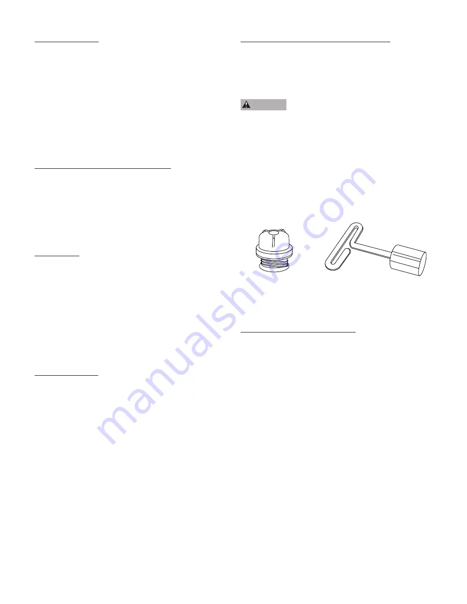
Poppet Assembly
T-Handle Poppet Wrench
REMOVABLE POPPET CHECK VALVE
4” submersible pumps with a 1-1/4” discharge are supplied
with a spring-loaded, removable poppet check valve assembly
(Figure 1). This check valve can be removed from the pump
discharge when drain back is desired.
W A R N I N G
Fluid draining back through the pump can
cause the pump to rotate backwards. If pump/motor starts
during this time, damage to the pump can occur.
The check valve can be removed using a T-handle poppet
wrench (purchased separately), or with standard needle-
nosed pliers. The poppet assembly is left-hand threaded and
is removed by turning clockwise. When reinstalling a poppet
check valve assembly, tighten it to 15 inch-pounds.
Содержание Little Giant 558223
Страница 6: ...THIS PAGE INTENTIONALLY LEFT BLANK 6...


