- 7 -
ZMI
_001_
2030
0204
53-A
Q
CT0073
_#SE
N
_#AQ
U
_#V
2.f
m
9.
Dimensions
10. Installation example
11. Spray pattern
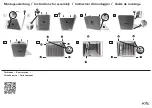
12. Assembly
Warning!
Only operate the fitting with non-return valves and the specified filters.
Failure to observe this instruction can result in an increased germ load in the
drinking water and thus pose a health or mortality risk.
Warning!
• Operate the product only with safety extra low voltage (SELV). The components
must not be earthed.
• Secure the mains power supply with a residual current circuit breaker (RCD).
Failure to observe this instruction can result in death or material damage due to
electric shock or fire, for example.
☞
Important!
Prior to the assembly process, flush the pipework in accordance with DIN 1988.
☞
To protect the tiles, use masking tape when marking and drilling. Drill at low speed.
☞
Depending on the composition of the wall, special wall plugs may have to be used
(to be provided by the customer).
Fig. A: Water connection from above
Fig. B: Water connection from the rear
12.1
Only for water connection from the rear: Install the connection bracket (b) leak-tight.
12.2
Screw in the water volume regulators (a) leak-tight.
12.3
Align the water volume regulators so that the locking screw and operating element
are freely accessible.
12.4
For a shower head height of 2.10 m to 2.30 m, mark drill holes for installation at a
height (c) of 2.12 m to 2.32 m from the top of the finished floor.
12.5
Drill holes in accordance with these markings.
12.6
Insert the wall plugs.
12.7
Screw on the suspension rail.
12.8
Suspend the shower panel.
12.9
Mark the remaining drill hole.


