Foxconn T99B226 Скачать руководство пользователя страница 4


general  safety  guidelines  only,  Foxconn  Industrial  Internet  assumes  no  liability  for 

customer’s failure to comply with safety precautions.   


FCC Exposure Limits 

The Federal Communications Commission (FCC) has established safety guidelines relating to 

RF transmitter  sites.  The  FCC  developed  limits  for  human  exposure,  known  as  Maximum 

Permissible Exposure (MPE) limits, in consultation with numerous other federal agencies. The 

standards  were  developed  by  expert  scientists  and  engineers  after  extensive  reviews  of 

scientific  literature  related  to  RF  biological  effects.  The  FCC  explains  that  its  standards 

incorporate prudent margins of safety. 

The human exposure limits are provided for two groups of potentially exposed people. 

Occupational  -  People  are  "exposed  as  a  consequence  of  their employment"  and  are  "fully 

aware of the potential for exposure and can exercise control over their exposure". 

General Population - Any people that "may not be made fully aware of the potential for exposure 

or cannot  exercise  control over  their  exposure".  This  group  does  not  receive  RF  Safety  & 

Awareness Training. 

Radio frequency radiation 

Cellular wireless products and devices operating over radio signals and the cellular products 

contains a transmitter and receiver. When it is ON, it receives and transmits radio frequency 

signals. Exposure to RF radiation may occur. 

Interference 

Cellular Wireless products and devices may cause interference, so please be aware of the 

restrictions on the use of wireless devices 


Содержание T99B226

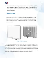
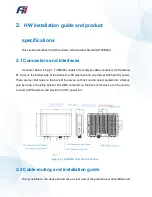
Страница 1: ...C Outdoor Small Cell CBRS...

Страница 2: ...ity including without limitation consequential or incidental damages neither does it convey any license under its patent rights nor the rights of others The information contained within this document...

Страница 3: ...ions If you have encountered an error please notify Foxconn Industrial Internet Product performance figures quoted within this document are indicative and for information purposes only All Intellectua...

Страница 4: ...man exposure limits are provided for two groups of potentially exposed people Occupational People are exposed as a consequence of their employment and are fully aware of the potential for exposure and...

Страница 5: ...ns 9 2 1 Connectors and Interfaces 9 2 2 Cable routing and installation guide 9 2 3 Product Specifications 16 3 Private Network Solution 18 3 1 Configuration Overview 18 3 2 Basic Setting 19 3 3 Advan...

Страница 6: ...24 3 6 Syslog 25 3 6 1 Syslog List 25 3 6 2 Syslog Files 26 3 6 3 Syslog Configuration 26 3 7 Reset Device 27 3 8 Diagnostic 27 4 LED display 28 5 Warranty and compliance 29 6 Frequently Asked Questi...

Страница 7: ...o radio television reception or WiFi AP which can be determined by turning the equipment on and off the technician is encouraged to try to correct the interference by performing one or more of the fol...

Страница 8: ...contains instructions and warnings that should be followed during installation and operation Failure to follow these instructions could cause bodily injury and or product failure Safety 1 Read this g...

Страница 9: ...pole mounted which makes it suitable to be deployed in a dense factory area both indoors and outdoors Figure 1 1 T99B226 Overview The LTE CA technology deployed in this outdoor small cell is compliant...

Страница 10: ...vice for LTE antennas and an ethernet RJ45 port for power There are four bolt holes on the back of the device so that it can be pole mounted onto a factory pole by using a mounting bracket The SMA con...

Страница 11: ...ennas are evenly distributed in the four corners In addition the GPS antenna should be positioned at a location where the GPS signal reception is solid and the wire connecting the GPS antenna to the d...

Страница 12: ...Figure 2 3 T99B226 assembly front view The installation instructions are specified in the steps below Figure 2 4 Installation setup...

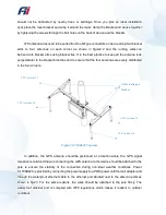
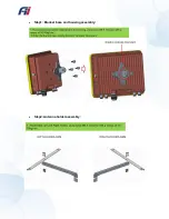
Страница 13: ...Step1 Bracket base and housing assembly Step2 Antenna holder assembly...

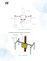
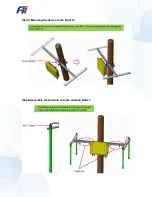
Страница 14: ...Step3 Assembly of the antenna holder with the bracket Step4 Mounting the bracket on a pole...

Страница 15: ...Step5 Mounting the device to the bracket Step6 Assemble the Antenna onto the antenna holder...

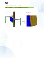
Страница 16: ...Step7 Assemble the Ground Screw on Device...

Страница 17: ...LTE Antenna Connector Four extendable N type RF antenna ports 6dBi omni directly antenna GPS Antenna Connector One extendable SMA type RF antenna port supply 5V for active GPS antenna WAN Interface Et...

Страница 18: ...ating IP65 Operation Humidity 20 90 Operation Temperature 40 50 Net Weight 2 5 kg Dimension 287 216 68 mm Reliability MTBF 20 years at room temperature Operating System need SW confirm Firmware Base o...

Страница 19: ...o configure the gateway The recommended browsers are Google chrome or Firefox for Small Cell configuration management to obtain the best display experience Connect the Ethernet port of the computer wi...

Страница 20: ...The Ethernet port should be configured according to the actual requirements when used for the first time Click Basic Setting WAN Configuration to enter the gateway network configuration and WAN Config...

Страница 21: ...bles the Small Cell to communicate with Auto Configuration Server ACS If the configuration of this setting is incorrect the Small cell will lack the ability to communicate with the configuration fault...

Страница 22: ...you are using Band 48 This means that the frequency range is from 3550MHz 3700MHz It is important to note that setting multiple small cells within the range of each other to the same frequency will c...

Страница 23: ...ll needs to be in constant contact with the EPC via an inform method This inform method carries with it the connection information configuration options and general Small Cell data When the small cell...

Страница 24: ...PTP sync Step 1 use MicroSemi IGM 1100i as the PTP master connect it to the GPS Antenna Step 2 ensure that IGM 1100i is synchronized with GPS signal Step 3 Turn on HeNB connect HeNB and PC with networ...

Страница 25: ...AS Enable the SAS in your small cell Figure 3 11 HeNB Running Mode 3 5 Firmware Upgrade Using File Transfer Protocol FTP to perform the firmware upgrade on the small cell Navigate to Firmware Upgrade...

Страница 26: ...n These events can be triggered by the user or by a running process They help you to keep track of all the activities and to troubleshoot problems Listed below are two of the most commonly seen error...

Страница 27: ...es The log in the small cell could be manually downloaded from here Figure 3 15 Syslog Files 3 6 3 Syslog Configuration The log can be automatically uploaded to your PC using an FTP server Figure 3 16...

Страница 28: ...You can manually reset the small cell to its default settings or to manually reboot it Figure 3 17 Reset Device 3 8 Diagnostic UE List of currently connected pieces of user equipment UE and the UE s...

Страница 29: ...ng Stay green Synchronization success Turn off No synchronization source LED4 Red Turn on No synchronization source Turn off Finded synchronization source resync status LED2 Green Turn on ethernet lin...

Страница 30: ...e The T99B226 Small Cell comes with a 5 year limited hardware warranty ITU 3GPP 3GPP E UTLA Release 9 IEEE IEEE 802 3u 100Base Ethernet IEEE 802 3ab Gigabit Ethernet Others Outdoor Rating IP65 Safety...

Страница 31: ...refer to Troubleshooting The chapter covers the following topics Why can t my device connect to the CBSD Outdoor Small Cell Ethernet PHY detection failed What is the setting to Connect to HeMS How to...

Страница 32: ...or 3 times if the situation still exists call the service center and replace the HeNB What is the setting to Connect to HeMS Go to Basic Settign page set the URL username and password of the serving H...

Страница 33: ...How to check the fault record Go to the path Syslog List to check the fault records...

Страница 34: ...tep1 for 3 times if the situation still persists call the service center and replace the HeNB Ethernet interface link is down 1 Check if the Ethernet cable on HeNB side or the uplink router side is lo...

Страница 35: ...Reboot the uplink router 4 Long press and hold the push button for 10 seconds and release the push button Wait for the HeNB to boot up DNS resolution failed 1 Check the internet connection on the upl...

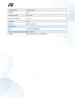
Страница 36: ...8 Packing information...

Страница 37: ...www fii usa com Visit our website or contact your local Fii representative for more information...

Отзывы: