


Chapter 2 Installation Instructions
14
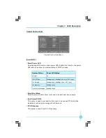
Additional COM Connector: COM2
This motherboard provides an additional serial
COM header for your machine.
Connect one side of a switching cable to the
header, then attach the serial COM device to the
other side of the cable.
COM2
SOUT
GND
RLSD
RI#
DTR#
DSR#
SIN
9
10
1
2
CTS#
RTS#
Empty
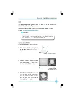
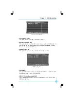
IrDA Connector: IR
This header supports wireless transmitting and
receiving device. Before using this function, con-
figure the settings of IR Mode from the
“
Integrated
Peripherals
”
section of the CMOS Setup.
1394 Connector:
F_1394 (optional)
The 1394 expansion cable can be connected to
either the front (provided that the front panel of
your chassis is equipped with the appropriate
interface) or real panel of the chassis.
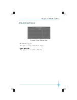
Speaker Connector: SPEAKER
The speaker connector is used to connect speaker
of the chassis.
SPEAKER
1
SPKJ
NC
SPKJ
Empty
1
2
GND
+12V
TPB -
GND
TPA -
+12V
TPB +
GND
TPA +
Empty
F_1394
9
10
IR
1
+5V
GND
IRRX
IRTX
Empty
文件使用
"pdfFactory"
试用版本创建
Æ
Æ
www.fineprint.com.cn