background image

Since BIOS could be updated some other times, the BIOS information described 
in this manual is for reference only. We do not guarantee the content of this 
manual will remain consistent with the newly released BIOS at any given time in 
the future. Please visit our website for updated manual if it is available.

This chapter tells how to change system settings through the BIOS 
Setup menus. Detailed descriptions of the BIOS parameters are 
also provided.
You have to run the Setup Program when the following cases oc-
cur:
1. An error message appears on the screen during the system 

Power On Self Test (POST) process.

2. You want to change the default CMOS settings.

This chapter includes the following information :

■        Enter BIOS Setup
■        Main Menu
■        System Information
■        Advanced BIOS Features
■ 

 THE CORE RELEASER

■        Fox Central Control Unit
■        Advanced Chipset Features 
■        Integrated Peripherals
■  

 Power Management Setup

■  

 PC Health Status 

■        BIOS Security Features 
■        Load Optimal Defaults
■        

Save Changes and Exit

■        

Discard Changes and Exit

Содержание A88GMX Series

Страница 1: ...A88GMX Series Motherboard User s Manual ...

Страница 2: ... indicates that this product may not be treated as household waste By ensuring this product is disposed of correctly you will help prevent potential negative consequences for the environment and human health which could other wise be caused by inappropriate waste handling of this product For more detailed information about recycling of this product please contact your local city office your househ...

Страница 3: ...adio disturbance characteristics of information technology equipment EN 61000 3 2 2000 Electromagnetic compatibility EMC Part 3 Limits Section 2 Limits for harmonic current emissions equipment input current 16A per phase EN 61000 3 3 A1 2001 Electromagnetic compatibility EMC Part 3 Limits Section 2 Limits of voltage fluctuations and flicker in low voltage supply systems for equipment with rated cu...

Страница 4: ...turer HON HAI PRECISION INDUSTRY COMPANY LTD Address 66 CHUNG SHAN RD TU CHENG INDUSTRIAL DISTRICT TAIPEI HSIEN TAIWAN R O C Supplementary Information This device complies with Part 15 of the FCC Rules Operation is subject to the following two conditions 1 this device may not cause harmful interference and 2 this device must accept any interference received including interference that may cause un...

Страница 5: ...ower please make sure the power supply AC input voltage setting has been configured to the local standard To prevent damage to the motherboard do not allow screws to come in contact with the motherboard circuit or its components Also make sure there are no leftover screws or metal components placed on the motherboard or within the computer casing If you are uncertain about any installation steps o...

Страница 6: ...9 System Information 21 Advanced BIOS Features 23 The core releaser 25 Fox Central Control Unit 26 Advanced Chipset Features 32 Integrated Peripherals 36 Power Management Setup 40 PC Health Status 42 BIOS Security Features 44 Load Optimal Defaults 45 Save Changes and Exit 45 Discard Changes and Exit 45 Chapter 4 CD Instruction Utility CD content 47 Install driver and utility 48 FOX ONE Main Page 5...

Страница 7: ...le in BIOS 81 Select a RAID Array for Use 81 Install a New Windows XP 93 Setting Up a Non Bootable RAID Array 97 Technical Support Website http www foxconnchannel com Support Website http www foxconnsupport com Worldwide online contact Support http www foxconnsupport com inquiry aspx CPU Support List http www foxconnsupport com cpusupportlist aspx Memory VGA Compatibility List http www foxconnsupp...

Страница 8: ...nly what you need for break through performance With advanced overclocking capability and a range of connectivity features for today multi media computing requirements A88GMX enables you to unleash more power from your computer This chapter includes the following information Product Specifications Layout Back Panel Connectors ...

Страница 9: ...4 1 Universal Video Decoder UVD 2 0 Storage SB710 chipset Support 5 x SATA connectors 300MB s data transfer rate Support RAID 0 1 10 and RAID JBOD Support hot plug and NCQ Native Command Queuing LAN Realtek 8111D VB GR Gigabit LAN chip Audio Realtek ALC887 GR audio chip High Definition Audio 2 4 5 1 7 1 channel Support for S PDIF Out Support Jack Sensing function USB Support hot plug Support up to...

Страница 10: ...ction CPU System NB fan speed detection CPU overheating warning CPU System NB fan speed control PCI Express x1 Support 500MB s 1GB s concurrent bandwidth Low power consumption and power management features PCI Express x16 Gen2 0 Support 8GB s 16GB s concurrent bandwidth Low power consumption and power management features Green Function Support ACPI Advanced Configuration and Power Interface Suppor...

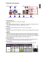
Страница 11: ... Connector 12 SATA Connectors 13 SYS_FAN Header 14 Clear CMOS Button 15 24 pin ATX Power Connector 16 Speaker Connector 17 FAN1 Header 18 IrDA Connector 19 DDR3 DIMM Slots 20 South Bridge AMD SB710 21 CPU Socket 22 North Bridge AMD 880G 23 8 pin ATX 12V Power Connector Note The above motherboard layout is for reference only please refer to the physical mother board for detail 5 6 8 7 21 1 20 4 10 ...

Страница 12: ... dio video to this port The HDMI Technology can support a maximum resolution of 1920x1080p but the actual resolutions supported depend on the monitor being used 6 External SATA Port To connect external SATA device s to your system by expanding the internal SATA port s to the chassis back panel External SATA device shall provide power by its own 7 RJ 45 LAN Port The Ethernet LAN port provides Inter...

Страница 13: ... channel 7 1 channel Blue Line In Line In Line In Line In Green Line Out Front Speaker Out Front Speaker Out Front Speaker Out Pink Microphone In Microphone In Microphone In Microphone In Orange Center Subwoofer Out Center Subwoofer Out Black Rear Speaker Out Rear Speaker Out Rear Speaker Out Grey Side Speaker Out ...

Страница 14: ...ut prior to any installation and read the contents in this chapter carefully This chapter includes the following information Install the CPU and CPU Cooler Install the Memory Install an Expansion Card Install other Internal Connectors Jumpers Please visit the following website for more supporting information about your motherboard CPU Support List http www foxconnsupport com cpusupportlist aspx Me...

Страница 15: ...to prevent hardware damage Locate the Pin 1 of the CPU The CPU cannot be inserted if oriented incorrectly Apply an even and thin layer of thermal grease on the surface of the CPU Do not turn on the computer if the CPU cooler is not installed otherwise overheating and damage of the CPU may occur Set the CPU host frequency in accordance with the CPU specifications It is not recommended that the syst...

Страница 16: ...ad an even thermal grease on the surface of CPU 2 Buckle the heatsink firmly at one side of the stand 3 Buckle the heatsink at another side and press the fasten lever down to tightly seat the cooler 4 Attach the 3 wire CPU cooler connector to the CPU fan header on the motherboard Use extreme care when removing the CPU cooler because the thermal grease may adhere to the CPU Inadequately removing th...

Страница 17: ...the following guidelines before you begin to install the memory Make sure that the motherboard supports the memory It is recommended that memory of the same capacity brand speed and chips be used Always turn off the computer and unplug the power cord from the power outlet before installing the memory to prevent hardware damage Memory modules have a foolproof design A memory module can be installed...

Страница 18: ...ory socket Place the memory module onto the socket then put your fingers on top edge of the module and push it down firmly and seat it vertically into the memory socket Step 2 The clips at both ends of the socket will snap into place when the memory module is securely inserted Before installing a memory module make sure to turn off the computer and unplug the power cord from the power outlet to pr...

Страница 19: ...y required BIOS changes for your expansion card s 7 Install the driver provided with the expansion card in your operating system Installing and Removing a PCI Express x16 Graphics Card Installing a Graphics Card Gently insert the graphics card into the PCI Express x16 slot Make sure the graphics card is locked by the latch at the end of the PCI Express x16 slot Removing the Card Push the latch at ...

Страница 20: ...make sure it is secure 8 pin ATX 12 V Power Connector PWR2 The 8 pin ATX 12V power supply connects to PWR2 and provides power to the CPU We recommend you using a 24 pin power supply If you are using a 20 pin power supply you need to align the ATX power connector according to the picture C A U T I O N 20 Pin Power Pin No 24 Pin Definition Pin Definition 1 3 3V 13 3 3V 2 3 3V 14 12V 3 GND 15 GND 4 5...

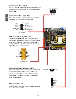
Страница 21: ...ically turned off after the system enters S3 S4 and S5 sleeping states COM Connector COM1 This motherboard supports one serial RS232 COM port for legacy compatibility User must purchase another RS232 cable with a 9 pin D sub connector at one end to connect with the external RS232 device and another end with 10 pin female connector to connect with COM1 connector in the motherboard Speaker Connector...

Страница 22: ...s The Power LED indicates the system s status When the system is in operation S0 status the LED is on When the system gets into sleep mode S1 the LED is blinking When the system is in S3 S4 sleep state or power off mode S5 the LED is off This 2 pin connector is directional with sign Power Switch Connector PWR SW Connect to the power button on the front panel of the chas sis Push this switch allows...

Страница 23: ... quickly expand another eight USB ports on the front panel Chassis Intruder Connector INTR The connector can be connected to a security switch on the chassis The system can detect the chas sis intrusion through the function of this connector If eventually the chassis is closed the system will send a message out IrDA Connector IR This connector supports infrared wireless transmit ting and receiving...

Страница 24: ...ous ESD Electrical Static Discharge problem Clear CMOS Jumper CLR_CMOS1 The motherboard uses CMOS RAM to store the basic hardware information such as BIOS data date time information hardware password etc Clear CMOS data is the fast way to go back to factory default when the BIOS settings were mistakenly modified The steps to clear CMOS data are 1 Turn off the computer unplug the power cord from th...

Страница 25: ...escriptions of the BIOS parameters are also provided You have to run the Setup Program when the following cases oc cur 1 An error message appears on the screen during the system Power On Self Test POST process 2 You want to change the default CMOS settings This chapter includes the following information Enter BIOS Setup Main Menu System Information Advanced BIOS Features the Core releaser Fox Cent...

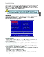
Страница 26: ...cking can be set up through this menu THE Core Releaser Enabled only if CPU supports The Core Releaser function can be set up through this menu Setting Options are Auto and Disabled Auto the 2 or 3 cores can be upgraded to 4 cores Disabled the system will downloading default CPU core When the message Press F3 to Setup Core Releaser appears at the bottom of the screen you can press F3 key to set th...

Страница 27: ...mal Defaults The optimal performance settings can be loaded through this menu However it may offer bet ter performance in some ways such as less I O cards less memory etc still it may cause problem if you have more memory or I O cards installed It means if your system loading is heavy set to optimal default may sometimes come out an unstable system What you need now is to adjust BIOS setting one b...

Страница 28: ...devices SATA1 is the lower SATA port of SATA1_SATA2 of the motherboard SATA2 is the upper SATA port of SATA1_SATA2 SATA3 is the lower SATA port of SATA3_SATA4 SATA4 is the upper SATA port of SATA3_SATA4 SATA5 is single SATA port of the motherboard e SATA is in the back panel Halt On This category determines whether or not the computer will stop if an error is detected during powering up CMOS Setup...

Страница 29: ...ll not stop for a mouse error if you enabled this item Model Name Model name of this product BIOS ID BIOS Version It displays the current BIOS ID version User can check this information and discuss with the field service people if a BIOS upgrade is needed Installed Memory Size This item displays the current memory size The size is depending on how many memory mod ules were installed in your system...

Страница 30: ...es are 32 64 96 128 160 192 224 248 This feature controls how long each PCI device can hold the bus before another takes over The larger the value the longer the PCI device can retain control of the bus Low values for the PCI Latency Timer will reduce the effective PCI bandwidth while higher values means every PCI device will have to wait longer before they can get access to the bus but when they ...

Страница 31: ...lows BIOS to skip certain tests while booting this will shorten the time needed to boot the system Bootup Num Lock This item defines if the keyboard Num Lock key is active when your system is started The available settings are On default and Off ...

Страница 32: ...ds Inc THE CORE RELEASER Advanced Clock Calibration Help Item AGESA Version 3 7 0 1 Physical Count 1 Logical Count 3 AMD Phenom tm II X3 700e Processor Cache L1 384KB Cache L2 1536KB Cache L3 6MB Current CPU Speed 2400MHz Current FSB Multiplier 12x Core Releaser NULL Move Enter Select Value F10 Save ESC Exit F1 General Help F9 Optimized Defaults Disabled Disabled Auto All Cores Per Core Options ...

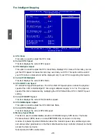
Страница 33: ...e empty PCI PCIE slot to reduce EMI Electromagnetic Interference Smart BIOS Fox Intelligent Stepping Voltage Options CPU Configuration Press Enter to go to the submenu CMOS Setup Utility Copyright C 1985 2006 American Megatrends Inc Fox Central Control Unit Super BIOS Protect Disabled Help Item Auto Detect PCI PCIE Clock Auto Smart BIOS Press Enter Fox Intelligent Stepping Press Enter Voltage Opti...

Страница 34: ...hout password trying to get into your computer through smart boot menu CMOS Setup Utility Copyright C 1985 2006 American Megatrends Inc Smart BIOS Smart Power LED Enabled Help Item Smart Boot Menu Enabled Smart Power LED definition Move Enter Select Value F10 Save ESC Exit F1 General Help F9 Optimized Defaults Disabled System Status Power LED Status Stop Blinking Condition Normal Always On Always ...

Страница 35: ...Multiplier Adjust This option is used to adjust the CPU NB Clock Ratio Current CPU NB Speed This item displays the current CPU NB speed Memory Speed Mode This item is used to enable disable provision of DRAM timing by SPD device The Serial Presence Detect SPD device is a small EEPROM chip mounted on a memory module It contains important information about the module s speed size addressing mode and...

Страница 36: ...emory Speed Mode is set to Limit or Manual The available settings are 800MHz 1067MHz 1333MHz 1600MHz Auto Current DRAM Speed This item displays the current DRAM speed GFX Engine Clock Override This item allows you to enable disable GFX Engine Clock Override support PCI Express Clock This option is used to adjust the speed of PCI Express slot It may enhance the graphics card speed Spread Spectrum I...

Страница 37: ...0mV to 270mV CMOS Setup Utility Copyright C 1985 2006 American Megatrends Inc Voltage Options CPU Voltage Offset Help Item Current CPU Voltage 1 248V Auto Target CPU Voltage 1 248V Auto Vcore offset the final vcore will be DRAM Voltage Offset 80mV the current idle or Current DRAM Voltage 1 616V 80mV load vcore ID plus Target DRAM Voltage 1 616V 80mV the offset increasing helps to overclock NB Core...

Страница 38: ...nction Default Value Select Auto BIOS will automatically determine to calibrate or not Select All Cores all cores will be calibrated at the same rate Select Per Core you can set different calibration rate for every core CMOS Setup Utility Copyright C 1985 2006 American Megatrends Inc CPU Configuration CPU Configuration Help Item Module Version 13 69 AGESA Version 3 7 0 1 Enable disable the Physica...

Страница 39: ...item shows the minimum timing interval between successive active commands to the same bank The row cycle time is in unit of clock cycle Internal Graphics Mode It allows you to determine whether to allocate memory for the integrated graphics controller from the system memory Options Disabled UMA Disabled Disables the integrated graphics controller UMA In UMA mode the only memory to which the integr...

Страница 40: ... that provides multi graphics controller display capability for both the ATI PCIe based graphics card and the ATI integrated graphics processor IGP Enabling SurroundView does not impact display modes resolution and color depth or perfor mance The display mode of each output is controlled independently by the graphics controller connected to it 1 When using a non ATI PCI Express PCIe graphics card ...

Страница 41: ...oth DCTs programmed identically Unganged channels DCT channels A and B operate as two completely independent 64 bit channels both chan nels operate at the same frequency Reduce DRAM page conflicts more concurrent open dram pages Better bus efficiency Burst lengths supported When both DCTs are enabled in unganged mode BIOS must initialize the frequency of each DCT in order CMOS Setup Utility Copyri...

Страница 42: ... DCT in order you also can configure the timings manually Settings are Auto DCT 0 DCT 1 Both CMOS Setup Utility Copyright C 1985 2006 American Megatrends Inc DRAM Timing Configuration DRAM Timing Configuration Help Item DRAM Timing Mode Auto DCT 0 DCT 1 Both Move Enter Select Value F10 Save ESC Exit F1 General Help F9 Optimized Defaults Options Auto ...

Страница 43: ...ng a boot ROM in the network board you can enable a client PC system on the network to be booted remotely HD Audio Controller This item is used to enable or disable the HD Audio Controller CMOS Setup Utility Copyright C 1985 2008 American Megatrends Inc Integrated Peripherals IDE Configuration Press Enter Help Item USB Configuration Press Enter SuperIO Configuration Press Enter Configure the IDE L...

Страница 44: ...es including SATA features but some SATA drives may not support AHCI unless they are labeled with AHCI support in its specification If your motherboard supporting AHCI and you have a SATA device which also supports AHCI then you can select IDE option to have fair performance only PATA SATA level or you can select AHCI to get its best performance Legacy IDE This configures the SATA ports to support...

Страница 45: ...his is a workround for OSes without EHCI hand off support The EHCI ownership change should claim by EHCI driver CMOS Setup Utility Copyright C 1985 2008 American Megatrends Inc USB Configuration USB Configuration Help Item Module Version 2 24 5 13 4 Enable support for legacy USB USB Devices Enabled Auto option disables None legacy support if no USB devices are Legacy USB Support Enabled connected ...

Страница 46: ...s BIOS to select mode for IR IR Duplex Mode This item enables you to determine the transfer mode of the onboard infrared chip CMOS Setup Utility Copyright C 1985 2006 American Megatrends Inc SuperIO Configuration SuperIO Configuration Help Item Serial Port1 Address Allows BIOS to select IR Address 2FB IRQ3 serial port1 base IR Mode IrDA address IR Duplex Mode Half Duplex Move Enter Select Value F1...

Страница 47: ... The S4 sleeping state is the lowest power longest wake latency sleeping state supported by ACPI In order to reduce power to a minimum it is assumed that the hardware platform has powered off all devices Platform context is maintained also called Suspend to Disk S5 The S5 state is similar to the S4 state except that the OS does not save any context The system is in the soft off state and requires ...

Страница 48: ... to generate a wake up Resume by PME This item is used to enable disable the PME to generate a wake up Resume by USB Devices This item is used to enable disable the USB Devices to generate a wake up Resume by PS2 Keyboard This item is used to enable disable the PS2 keyboard to generate a wake up Resume by RTC This item is used to enable disable RTC alarm event to generate a wake up RTC is system r...

Страница 49: ...unction System Smart Fan Function to Enabled the following items will appear Off PWM Temperature This item is used to set a off limit of temperature The fan will stop when the temperature is lower than the off limit You can input a value from 0 to 127 or change it by pressing key Start PWM Temperature This item is used to set a start limit of temperature The fan will start to spin when the tempera...

Страница 50: ...an initial PWM value to drive the fan when the temperature reaches Start PWM Temperature value Slope PWM Value It is used to set a slope value in PWM Temperature diagram The PWM value is subject to the temperature input value by linear changing ...

Страница 51: ...s item is used to enable disable boot sector virus protection CMOS Setup Utility Copyright C 1985 2006 American Megatrends Inc BIOS Security Features Scurity Settings Help Item Supervisor Password Not Installed Enter or change the User Password Not Installed password Change Supervisor Password Press Enter Change User Password Press Enter Boot Sector Virus Protection Disabled Move Enter Select Valu...

Страница 52: ...o be set cannot be supported by your hardware devices for example too many expansion cards were installed the system might fail to work Save Changes and Exit When you select this option and press Enter a message will be displayed in the center of the screen Select OK to save your changes to CMOS and exit the program select Cancel or ESC to return to the main menu Discard Changes and Exit If you se...

Страница 53: ...he mother board features This chapter includes the following information Utility CD content Install driver and utility FOX ONE FOX LiveUpdate FOX LOGO FOX DMI Browser Configuration Utility Note Because each module is independent so the section number will be reorganized and unique to each module please understand ...

Страница 54: ... VGA Driver E AMD RAID Driver 1 F ATI HDMI Audio Driver 2 Software Utilities Use these options to install additional software programs FOX ONE is a very powerful user interface program which allows you to change your system setting without going to BIOS Some auto features help user to improve or overclock your system without being a computer literate A FOX ONE B FOX LiveUpdate C FOX LOGO D FOX DMI...

Страница 55: ...e Click Setup and then choose the items you want to install or you can click on each individual driver to install it manually Choose the items you want to Install Manual Installation Step by Step Select to Install Utilities Select to Install Drivers Click to visit Foxconn s website Browse CD View the Utility Help files Automatic Installation by One Click Drop to System Tray Exit the program ...

Страница 56: ...4 49 2 Install Utility Use these options to install additional software programs 3 Utility Help Click this button to view the utility FOX ONE FOX LiveUpdate FOX LOGO FOX DMI help manual ...

Страница 57: ...elligent Stepping will require you to calibrate the CPU s loading Click OK to proceed and start the Utility F I S is a feature of FOX ONE which can automatically adjust your CPU clock based on your current system loading Before you running the FOX ONE program the system parameters such as CPU clock voltage etc are controlled by BIOS settings After you run FOX ONE it will take over and the controll...

Страница 58: ...plify the whole FOX ONE control panel to a smaller information bar i e Simple Mode as depicted below you can drag this bar to any place on your screen to help you monitoring system status Click here to go back to FOX ONE full screen Click here will drop the FOX ONE to Windows system tray Exit FOX ONE Show CPU Information Toolbar Alert Lamp Switch Button Exit Minimum Homepage Monitor Frequency Volt...

Страница 59: ...t Click this button to exit the program Minimum Click this button to drop the FOX ONE to Windows system tray located at the lower right corner of your screen Homepage Click this button to visit Foxconn motherboard website http www foxconnchannel com Apply the changes Click the new skin picture to select the new skin Cancel the changes ...

Страница 60: ...e Simple Mode Messages such as CPU frequency voltage etc they can be displayed one by one in Simple Mode 3 F I S Calibration FOX Intelligent Stepping Optional This function will re calibrate the CPU s loading and it may take several minutes to proceed The FOX ONE calibration process will apply different loadings to your CPU record PWM IC voltage together with the CPU clock running at these loading...

Страница 61: ... After data is collected it will ask you to restart your computer now Later on when the FOX ONE program is activated and F I S feature in CPU Page is also enabled FOX ONE will automatically adjust your CPU clock according to your system loadings Loadings are like Power Gaming Data Mining etc ...

Страница 62: ...eck the highest CPU clock you can use System will raise the CPU clock step by step until it hangs you can then push the RESET button on your PC panel to restart the system When system restarts run FOX ONE again it will display a recommended highest CPU clock for you click Yes to apply it A message informs you to push RESET button later if the system hangs finally Click Yes to continue Press Auto b...

Страница 63: ...ET button on the front panel of your system to restart the computer Run FOX ONE program again it will inform you the previous test found that 255MHz is the recommended CPU clock for your system Click Yes to apply it to your system Now your system is running at a CPU clock of 215MHz ...

Страница 64: ... speed to a minimum The four benchmarks Power Gaming Data Mining Office and Energy Saving the references of their system loading were calculated and defined in the FIS Calibration option of Configuration menu Select Auto CPU will automatically adjust its clock according to current system loading 3 Frequency Page Frequency Control This page lets you set memory and PCI Express frequencies by manual ...

Страница 65: ...ert function Go to Limit Setting page Set high limit by dragging the lever Show current CPU temperature value Enable alert function when the CPU temperature is higher than high limit value Show current high limit value of the CPU temperature Set high limit by dragging the lever Show current system temperature value Enable alert function when the system temperature is higher than high limit value S...

Страница 66: ...ert function Set low limit rpm by dragging the lever Show current CPU fan rpm value Enable alert function when the CPU fan runs slower than the low limit rpm value Show current low limit rpm value of CPU fan Set low limit rpm by dragging the lever Show current system fan rpm value Enable alert function when the system fan runs slower than low limit rpm value Show current low limit rpm value of sys...

Страница 67: ...age manually CPU voltage can be stepped up down by a unit of 12 5mV while memory is 0 05V step and North Bridge is 0 04V step Set low limit rpm by dragging the lever Show current NB fan rpm value Enable alert function when the NB fan runs slower than low limit rpm value Show current low limit rpm value of NB fan Go to Voltage page Select the option you want to set Adjust by manual Reset the change...

Страница 68: ...s you enable Smart Fan function or set the fan speed by manual When Smart Fan is selected you must use a 4 pin CPU cooler in your system Go to Fan page Set fan speed by dragging the lever Enable or disable smart fan function Apply the changes ...

Страница 69: ...ws 2000 Windows XP 32 bit and 64 bit Windows 2003 32 bit and 64 bit Windows Vista 32 bit and 64 bit Windows 7 32 bit and 64 bit Using FOX LiveUpdate 1 Local Update 1 1 Local Update BIOS Information This page lets you know your system BIOS information please refer to the physical motherboard for detail Exit Toolbar Minimum Show current BIOS information Link to website ...

Страница 70: ...sure if you really want to continue click Yes to confirm A setup wizard will guide you to load a local BIOS file to finish the operation You must remember from which directory to load your new BIOS file with an extension of BIN for Award BIOS ROM for AMI BIOS before the setup wizard starts Key in a BIOS name Click here FOX LiveUpdate can automatically backup old BIOS before update This feature can...

Страница 71: ...ation 2 2 Online Update Update Driver This page lets you update your system drivers from Internet Click start it will search the new drivers from Internet Then follow the wizard to finish the update operation Click here Current information Search new BIOS from Internet Browse detailed information Update BIOS Close the window Select BIOS to update Click here Current information Search new drivers f...

Страница 72: ...rom Internet Then follow the wizard to finish the update operation Browse detailed information Install the selected driver Close the window Select the driver to update Click here Current information Search new utilities from Internet Browse detailed information Install the selected utility Close the window Select the utility to update ...

Страница 73: ...ll search all new BIOS drivers utilities from Internet Then follow the wizard to finish the update operation Click here Current information Search all new BIOS drivers utilities from Internet Browse detailed BIOS information Close the window Browse detailed driver information Browse detailed utility information ...

Страница 74: ...m Internet and if any qualified item found it will pop out a message on the task bar to inform you to do the next step Double click on the icon as show below you can see the detailed information Double click here Apply the changes Reset to default value Click here Set auto search options Select search which kind of versions Set auto search the latest FOX LiveUpdate ...

Страница 75: ...e System This page lets you set the location of download files and auto backup BIOS determine if the FOX LiveUpdate can auto run when the system starts up Prompt you to install the new FOX LiveUpdate Click here Set the location of download files or auto backup BIOS Determine if the FOX LiveUpdate can auto run when the system starts up Apply the changes Reset to default value ...

Страница 76: ...out any interruption 4 About Help This page shows some information about FOX LiveUpdate C A U T I O N We recommend that you had better keep the default setting unchanged to avoid any damage Click here Select which BIOS ROM to flash Only available to motherboard with backup BIOS ROM Apply the changes Reset to default value Select to flash Boot Block Select to clear CMOS Click here Show information ...

Страница 77: ...ble the BIOS Quiet Boot setting in Advanced BIOS Features menu Supporting Operating Systems Windows 2000 Windows XP 32 bit and 64 bit Windows 2003 32 bit and 64 bit Windows Vista 32 bit and 64 bit Windows 7 32 bit and 64 bit Using FOX LOGO Main Page When you change Logo or delete current Logo the system will flash BIOS file auto matically During this time please DO NOT shut down the application an...

Страница 78: ...ze and troubleshoot your mother board if there is any problem occurred Supporting Operating Systems Windows 2000 Windows XP 32 bit and 64 bit Windows 2003 32 bit and 64 bit Windows Vista 32 bit and 64 bit Windows 7 32 bit and 64 bit Using FOX DMI Please operate this utility as the comments shows Click here to select the DMI Data format you need Click here to select the node you want to view ...

Страница 79: ...ll appear in the search menu of browser You can use it directly 2 If you have installed another search engine the Browser Configuration Utility will send out a dialog to ask Do you want to change your browser search engine to Yahoo If you want to use Yahoo engine as the default Select Yes and click OK Then you will see a END USER LICENSE AGREEMENT Read it and select I agree to change your default ...

Страница 80: ... 7 system with new RAID built as data storage It includes the following information RAID Configuration Introduction Option ROM Utility Create a RAID Driver Diskette RAID Enable in BIOS Select a RAID Array for use Install a New Windows XP Setting up a Non Bootable RAID Array The RAID BIOS Setup pictures shown in this chapter are for refer ence only please refer to the practical screen ...

Страница 81: ... To create RAID driver diskette if it is not bundled 6 Windows XP Vista or 7 Install CD Creating a Non Bootable Array Existing Windows XP or Vista 7 system with new RAID built as data storage Follow 5 5 to go through the processes to build a new RAID array in your existing Windows XP system it includes 1 Set RAID enabled in BIOS 2 Follow 5 3 to select a RAID array for use 3 Run setup program to in...

Страница 82: ...rtant for example a system that delivers video on demand TV programs to many viewers The configuration affects reliability and performance in different ways The problem with using more disks is that it is more likely that one will go wrong but by using error checking the total system can be made more reliable by being able to survive and repair the failure Basic mirroring can speed up reading data...

Страница 83: ...ut you need four SATA hard disks Span JBOD JBOD stands for Just a Bunch of Disks Each drive is accessed as if it were on a standard SCSI host bus adapter This is useful when a single drive configuration is needed but it offers no speed improvement or fault tolerance A spanned volume is a formatted partition which data is stored on more than one hard disk yet appears as one volume Unlike RAID spann...

Страница 84: ...per SATA port of SATA1_SATA2 Port 3 is the lower SATA port of SATA3_SATA4 Port 4 is the upper SATA port of SATA3_SATA4 To achieve the best performance and reliability we highly recommend you using the hard disks with the same brand size and model number Though we are using four different hard disks as an example to describe RAID function in this chapter it is only helpful in explaining what the fi...

Страница 85: ...xisting Windows XP system with new RAID built as data storage Install SATA Hard Disks before we continue Shut down your computer Install SATA hard disks into the drive bays connect all power and SATA cables Before installing the SATA hard disks make sure to turn off the computer and unplug the power cord from the power outlet to prevent damage to the hardware C A U T I O N ...

Страница 86: ...Driver AMD RAID Floppy WinXP click on RaidTool icon to start the creation 3 Click GO to start 4 Select the desired destination FDD drive It can be the default drive A or any USB FDD Click OK to continue 5 Insert a diskette click OK to continue 5 1 Create a RAID Driver Diskette If you want to install a brand new Windows XP on a RAID system you need to create a RAID driver floppy diskette which will...

Страница 87: ...e label for this diskette click on Start to format 7 Click on OK to go through this warning message 8 Format finished Click OK to continue copying of RAID driver into this diskette 9 Check if the diskette contains the driver files ...

Страница 88: ...isplay a message asking you to press Ctrl F key to enter the main menu of Option ROM Utility Press Ctrl F the Main Menu appears Option ROM Utility c 2008 Advanced Micro Devices Inc View Drive Assignments 1 LD View LD Define Menu 2 Delete LD Menu 3 Controller Configuration 4 Main Menu Press 1 4 to Select Option ESC Exit Keys Available CMOS Setup Utility Copyright C 1985 2006 American Megatrends Inc...

Страница 89: ...Define LD Menu Keys Available LD View Menu Option ROM Utility c 2008 Advanced Micro Devices Inc LD No LD Name RAID Mode Drv LD 1 Logical Drive 1 RAID 0 2 Stripe Block 64 KB Fast Init ON Gigabyte Boundary ON Cache Mode WriteThru Port ID Drive Model Compatibilities Capacity GB Assignment 1 Mas HDS728090PLA380 SATA 3G 82 34 Y 2 Mas WDC WD1200JD 98HBB0 SATA 1 5G 120 03 Y 3 Mas Hitachi HDT725025VLA3 SA...

Страница 90: ...ss Ctrl Y to Modify Array Capacity or press any other key to use maximum capacity Fast Initializing LD No LD Name RAID Mode Drv LD 1 Logical Drive 1 RAID 0 2 Stripe Block 64 KB Fast Init ON Gigabyte Boundary ON Cache Mode WriteThru Port ID Drive Model Compatibilities Capacity GB Assignment 1 Mas HDS728090PLA380 SATA 3G 82 34 Y 2 Mas WDC WD1200JD 98HBB0 SATA 1 5G 120 03 Y 3 Mas Hitachi HDT725025VLA...

Страница 91: ...e LD Menu Option ROM Utility c 2008 Advanced Micro Devices Inc Keys Available RAID 0 Define LD Menu Drives Assignment Enter array capacity in GB here 6 Press Ctrl Y Input 80GB to select the first logical drive LD1 and press Enter 7 The selection of LD1 array is completed As we want to introduce how to create two logical drives by using the same two hard drives here so we will press Crtl C to defin...

Страница 92: ...able Define LD Menu Drives Assignment Y 9 Press Ctrl Y to save the setting And a message prompts You kann select any of the two options Here we select the latter option as an example LD No LD Name RAID Mode Drv LD 2 Logical Drive 2 RAID 0 2 Stripe Block 64 KB Fast Init ON Gigabyte Boundary ON Cache Mode WriteThru Port ID Drive Model Compatibilities Capacity GB Assignment 1 Mas HDS728090PLA380 SATA...

Страница 93: ...Utility c 2008 Advanced Micro Devices Inc Fast Initialization Option has been selected It will erase the MBR data of the disks Press Ctrl Y Key if you are sure to erase it Press any other key to ignore this option 10 Another message prompts Press Ctrl Y to erase the RAID array 11 The remaining disk spaces are assigned to LD2 The size is about 42GB 2 84GB LD No RAID Mode Drv Capacity GB Status LD 1...

Страница 94: ...AS SATA 1 5G 320 07 Y Up Down PaUp PaDn Switch Page Space Change Option Ctrl Y Save ESC Exit Define LD Menu Define LD Menu Drives Assignment Option ROM Utility c 2008 Advanced Micro Devices Inc Please press Ctrl Y key to input the LD name or press any key to exit If you do not input any LD name the default LD name will be used Keys Available LD No LD Name RAID Mode Drv LD 1 Logical Drive 1 RAID 1 ...

Страница 95: ... SATA 1 5G 120 03 N 3 Mas Hitachi HDT725025VLA3 SATA 3G 250 05 Y 4 Mas ST3320620AS SATA 1 5G 320 07 Y Up Down PaUp PaDn Switch Page Space Change Option Define LD Menu Define LD Menu Drives Assignment Option ROM Utility c 2008 Advanced Micro Devices Inc Press Ctrl Y to Modify Array Capacity or press any other key to use maximum capacity Fast Initializing LD No RAID Mode Drv Capacity GB Status LD 1 ...

Страница 96: ...ST3320620AS SATA 1 5G 320 07 Y Up Down PaUp PaDn Switch Page Space Change Option Ctrl Y Save ESC Exit Define LD Menu Define LD Menu Drives Assignment Option ROM Utility c 2008 Advanced Micro Devices Inc Please press Ctrl Y key to input the LD name or press any key to exit If you do not input any LD name the default LD name will be used Keys Available LD No LD Name RAID Mode Drv LD 1 Logical Drive ...

Страница 97: ...D1200JD 98HBB0 SATA 1 5G 120 03 N 3 Mas Hitachi HDT725025VLA3 SATA 3G 250 05 Y 4 Mas ST3320620AS SATA 1 5G 320 07 Y Up Down PaUp PaDn Switch Page Space Change Option Define LD Menu Define LD Menu Drives Assignment Option ROM Utility c 2008 Advanced Micro Devices Inc Press Ctrl Y to Modify Array Capacity or press any other key to use maximum capacity Fast Initializing LD No RAID Mode Drv Capacity G...

Страница 98: ...HDT725025VLA3 SATA 3G 250 05 Y 4 Mas ST3320620AS SATA 1 5G 320 07 Y Up Down PaUp PaDn Switch Page Space Change Option Ctrl Y Save ESC Exit Define LD Menu Keys Available Define LD Menu Drives Assignment Y Option ROM Utility c 2008 Advanced Micro Devices Inc LD No LD Name RAID Mode Drv LD 1 Logical Drive 1 JBOD 4 Stripe Block NA Fast Init ON Gigabyte Boundary ON Cache Mode WriteThru Port ID Drive Mo...

Страница 99: ...0620AS SATA 1 5G 320 07 Y Up Down PaUp PaDn Switch Page Space Change Option Ctrl Y Save ESC Exit Define LD Menu Define LD Menu Drives Assignment Option ROM Utility c 2008 Advanced Micro Devices Inc Fast Initialization Option has been selected It will erase the MBR data of the disks Press Ctrl Y Key if you are sure to erase it Press any other key to ignore this option Keys Available LD No RAID Mode...

Страница 100: ...ll go to an fatal blue screen and you may need to reboot the system again PC may not respond to your F6 input immediately and it keeps loading files until the next screen displays Windows Setup Press F6 if you need to install a 3rd party SCSI or RAID driver CMOS Setup Utility Copyright C 1985 2006 American Megatrends Inc Boot Device Priority Boot Device Priority Item Help 1st Boot Device CDROM Spe...

Страница 101: ...ine the type of one or more mass storage devices installed in your system or you have chosen to manually specify an adapter Currently Setup will load support for the following mass storage device s none To specify additional SCSI adapters CD ROM drivers or special disk controllers for use with Windows including those for which you have a device support disk from a mass storage device manufacturer ...

Страница 102: ...have a device support disk from a mass storage device manufacturer press S If you do not have any device support disks from a mass storage device manufacturer or do not want to specify additional mass storage devices for use with Windows press ENTER S Specify Additional Device ENTER Continue F3 Exit Windows Setup You have chosen to configure a SCSI Adapter for use with Windows using a device suppo...

Страница 103: ...ed space on this computer Use the UP ad DOWN ARROW keys to select an item in the list To set up Windows XP on the selected item press ENTER To create a partition in the unpartitioned space press C To delete the selected partitions press D 238410 MB Disk 0 at Id 1 on bus 0 on ahcix86 MBR ENTER Install C Create Partition F3 Quit Unpartitioned space 238410 MB Windows XP Professional Setup The followi...

Страница 104: ...port1 1 Reboot your system and go to IDE Configuration menu Enable the RAID function Press F10 to save the settings and reboot To achieve the best performance and reliability we highly recommend you using the hard disks with the same brand size and model number Though we are using different brand of hard disks as an example here the purpose is only for easy understanding W ARNING CMOS Setup Utilit...

Страница 105: ... In Windows click Cancel to skip any Found New Hardware Wizard Use driver CD and click on AMD RAID Driver to install the AMD RAID driver The RAID driver will be installed only when you select RAID in OnChip SATA Type setting If you do not select RAID then RAID driver will not be installed LD No RAID Mode Drv Capacity GB Status LD 1 RAID 0 2 249 99 Functional Up Down PaUp PaDn Switch Page Ctrl C De...

Страница 106: ...5 99 5 After the AMD RAID driver is installed it will ask you to click Finish to restart your computer 6 When Windows starts a message is prompting you to reboot again Click Yes to restart your computer ...

Страница 107: ...e and Convert Disk Wizard appears Click Next to continue The RAID array is named as Disk1 and its status is unknown and not initialized 8 A Select Disks to Initialize window will appear The disks listed depend on how many arrays you have configured Select Disk1 and click Next to continue 9 When Select Disks to Convert window appears do not select anything and click Next to continue 10 When the Com...

Страница 108: ...efore using it Right click Unallocated space select New Partition and follow the Wizard instructions 12 When New Partition Wizard appears click Next to continue 13 When Primary partition screen appears click Next to continue 14 When Specify Partition Size screen appears click Next to continue 15 When Assign Drive Letter or Path screen appears click Next to continue 16 Click Finish to end the New P...

Страница 109: ...5 102 17 The format of disk array Disk1 is in processing 18 Format completed now you can start using your RAID array ...

Отзывы: