


Chapter 2 Installation Instructions
14
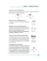
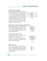
Front Panel Connector: FP1
This motherboard includes one connector for connect-
ing the front panel switch and LED indicators.
IDE LED Connector (HD-LED)
The connector connects to the case
’
s IDE indicator
LED indicating the activity status of hard disks.
Reset Switch (RESET)
Attach the connector to the Reset switch on the front
panel of the case; the system will restart when the
switch is pressed.
Power LED Connector (PWRLED)
Attach the connector to the power LED on the front
panel of the case. The Power LED indicates the
system
’
s status. When the system is in S0 status, the
LED is on. When the system is in S1 status, the LED
is blink; When the system is in S3, S4, S5 status, the
LED is off.
Power Switch Connector (PWRSW)
Attach the connector to the power button of the case.
Pushing this switch allows the system to be turned on
and off rather than using the power supply button.
FP1
NC
HD-LED
PW R LED
PW R SW
Emp ty
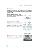
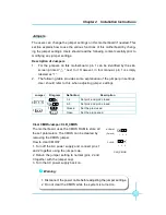
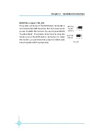
Fan Connectors: CPU_FAN, SYS_ FAN
The fan speed of CPU_FAN and SYS_FAN can be
detected and viewed in
“
PC Health Status
”
section of
the CMOS Setup. These fans will be automatically
turned off after the system enters S3, S4 and S5 mode.
Plug the CPU cooling fan cable into the 4-pin CPU
FAN power supply on the motherboard. Connect the
case cooling fan connector to SYS_FAN.
SYS_FAN
+12V
GROUND
SENSE
1
CPU_FAN
SENSE
POWER
GROUND
1
CONTROL
+ -
+ -
1
R E S E T