


17
Chapter 2 Installation Instructions
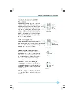
Hard Disk LED Connector (HDD_LED)
Attach the connector to the HDD_LED on the front panel of the case; the LED will
flash while the HDD is in operation.
Reset Switch (RESET)
Attach the connector to the Reset switch on the front panel of the case; the
system will restart when the switch is pressed.
Power LED Connector (PLED)
Attach the connector to the Power LED on the front panel of the case. The Power
LED indicates the power supply status. When the system is in S0 status, the
LED is on. When the system is in S1 status, the LED is blink. When the system
is in S3, S4, S5 status, the LED is off.
Power Switch Connector (PWRBTN#)
Attach the connector to the power button of the case. Pushing this switch allows
the system to be turned on and off rather than using the power supply button.
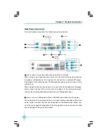
USB Connectors: F_USB 1, F_USB 2
Besides four USB ports on the rear panel, the series of motherboards also have
two 10-pin headers on board which may connect to the front panel USB cable to
provide additional four USB ports.
F_USB1
D5-
VCC
D4+
D4-
Empty
GND
NC
VCC
GND
D5+
1 2
9 10
F_USB2
D7-
VCC
D6+
D6-
Empty
GND
NC
VCC
GND
D7+
1 2
9 10
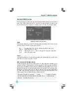
Fan Connectors: CPU_FAN, SYS_FAN
The fan speed of CPU_FAN and SYS_FAN can be detected and viewed in
“
PC
Health
”
section of the CMOS SETUP. These fans will be automatically turned off
after the system enters suspend mode.
SYS_FAN
SENSE
+12V
GND
1
+12V SENSE
GND
1
CPU_FAN
文件使用
"pdfFactory"
试用版本创建
Æ
Æ
www.fineprint.com.cn