


-2-
Part-2 Y-axis Stepper Motor Assembly
Required
Parts
No.
Name
QTY
Picture
2.
Y-axis Base
1
3.
42 Stepper Motor
1
19.
M3*12 Bolt
4
22.
Φ3 Gasket
4
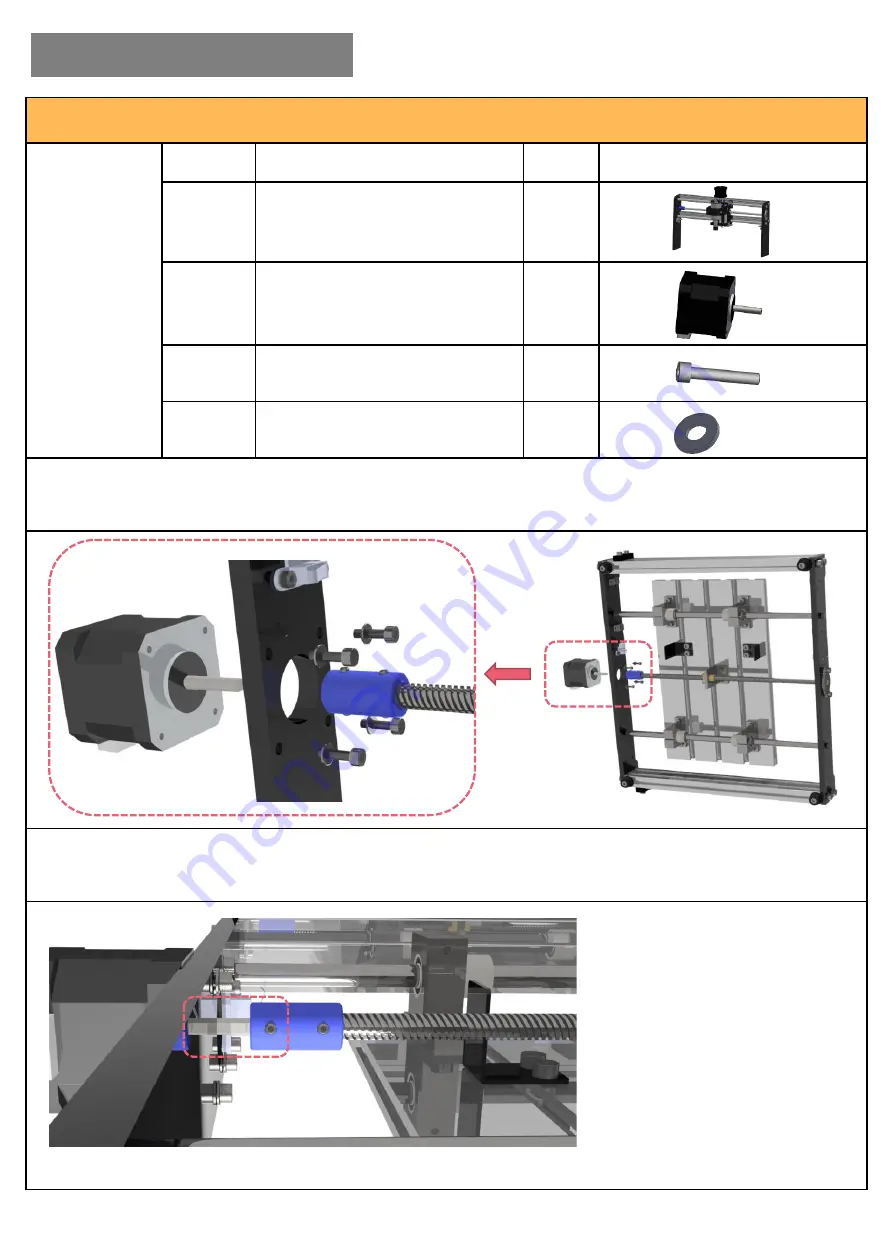
Step 1:
Assemble the Y-axis stepper motor as following pictures. Fix the motor to the back of the base
with M3*12 bolts and gaskets.
Note: the wire port should face to the right.
Step 2:
Connect the lead screw to the stepper motor with set screw.
Note: fasten the set screw to the flat side of the motor shaft.
I. Hardware Assembly


