background image

Model

Introduction

Thank you very much for purchasing the Fostex VM88.
Please read the following to get the most satisfaction from your purchase, and to
learn important information about safety precautions when using Fostex prod-
ucts.

The VM88 digital mixer does all internal signal processing digitally.
The input features 8 analog channels, of which 4 channels (XLR or PHONE) are for
microphones; digital inputs (S/P DIF or ADAT) via optical connection are provided.
For outputs, an optical digital output (S/P DIF or ADAT) in addition to stereo out
(balanced/unbalanced), headphone out, AUX send/out and monitor outs in analog
are also provided.  An insert function is featured in channels 1 - 4 for more
flexibility during mixing.

In addition to each input channel, an three band EQ is also provided for the
master output.  The VM88 also incorporates high performance DSP multi-effects
on two channels that operate by A.S.P. (Fostex Advanced Signal Processing Tech-
nology*) exclusively developed by Fostex.  This allows a wide range of equalizing
and effects processing.  All settings, including mix and effects settings, are stored
in scene memory, and a desired scene memory can be recalled instantaneously.
Although small and lightweight, the VM88 is a high performance unit.  Please
read this manual carefully before operation to understand all functions of the
VM88.

* See page 24 for more details on the A.S.P. (Fostex Advanced Signal Processing Technology).

Eight Channel Digital Mixer with DSP Effects

Owner’s Manual

Содержание VM88

Страница 1: ... function is featured in channels 1 4 for more flexibility during mixing In addition to each input channel an three band EQ is also provided for the master output The VM88 also incorporates high performance DSP multi effects on two channels that operate by A S P Fostex Advanced Signal Processing Tech nology exclusively developed by Fostex This allows a wide range of equalizing and effects processi...

Страница 2: ...rization The precautions that should be taken so that the grounding or polarization means of an appliance is not defeated The lightning flash with arrowhead symbol within an equilateral triangle is intended to alert the user to the presence of uninsulated dangerous voltage within the product s enclosure that may be of sufficient magnitude to constitute a risk of electric shock to persons The excla...

Страница 3: ...se read before use Table of Contents Precautions 2 Names and Functions 4 Top panel section 4 Rear panel section 7 Block Diagram 7 Before Operation 8 Remove the insulation paper 8 Reset of VM88 8 Internal battery for the memory back up 8 Peripheral Equipment Connection 9 Application Examples 12 Initial State of the VM88 14 NormalMixMode 15 Muting the input master channels 16 On and off of the stere...

Страница 4: ...e trimmed the same as with MIC 1 4 within a range of 30dBu 10dBu For details please refer to Connecting peripheral equipment on page 9 2 AUX send jack AUX SEND level signal adjusted in the channel parameter edit mode is output here For details on adjusting the output signals refer to Channel parameter edit mode on page 20 3 Stereo out connector The mixed signal to be input to an MTR or other mixer...

Страница 5: ...pressed while pressing the EXIT key muting of EFF 2 can be switched ON OFF Refer to Effect edit mode on page 24 for details 16 Effect 1 key This is pressed to select the EFF 1 effects type or the parameter to be edited Also if this key is pressed while pressing the EXIT key muting of EFF 1 can be switched ON OFF Refer to Effect edit mode on page 24 for details 17 Enter key This is used to accept t...

Страница 6: ...ting the input gain to match the sound source connected to INPUT 1 8 These can be adjusted within the range of 50dBu 10dBu for MIC INPUT 1 4 30dBu 10dBu for LINE INPUT 1 4 and 40dBu 4dBu for INPUT 5 8 31 Input jack 5 8 Line level sound sources can be connected to channels 5 8 input jacks TRS phone jacks In the initial setup the input mode of INPUT 5 6 and INPUT 7 8 are set to stereo so that stereo...

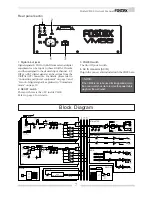
Страница 7: ...GITAL EFFECT EFF 1 2 ST MASTER D A D A To METER ST MASTER PHONES 100mW ST OUT 10dBV L R L R EFF TRIM EFF 2 AUX 1 AUX 2 CH ON 1kHz MID CH5 6 A D LO HI PRE POST GAIN PAN EFF 1 10kHz 100Hz To METER EFF 2 AUX 1 AUX 2 CH ON 1kHz MID A D AUX MASTER D A D A AUX 1 OUT 10dBV ST 1 2 AUX 1 2 AUX 1 MASTER AUX 2 MASTER EFF 1 MASTER EFF MUTE LO HI 10kHz 100Hz CH ON 1kHz MID MONO STEREO SETUP CH7 8 CH 2 CH 3 CH ...

Страница 8: ...s Please remember If reset is executed with the INPUT and MASTER raised simultaneous with start up of this unit the LEVEL ADJUST key FADER ADJUST key will blink This indicates that the VM88 has entered the Level Adjust Mode Fader Adjust Mode because of the difference between present fader position and the fader position at start up following reset To exit from this mode retard all faders to the MI...

Страница 9: ...dBu 4 4 40 40 dBu dBu 4 4 40 40 8 7 6 5 dBu dBu 10 10 10 10 50 50 30 30 dBu dBu 10 10 10 10 50 50 30 30 dBu dBu 10 10 10 10 50 50 30 30 MIC MIC LINE LINE MIC MIC LINE LINE MIC MIC LINE LINE INSERT INSERT INSERT LINE LINE LINE LINE dBu dBu 10 10 10 10 50 50 30 30 MIC MIC LINE LINE INSERT LINE MIC MIC 4 3 2 1 2 HOT MIC MIC 2 HOT MIC MIC AUX SEND AUX SEND ST ST OUT OUT MON IN MON IN MON OUT MON OUT F...

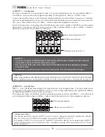
Страница 10: ...Initially set at off For details refer to Setup mode on page 33 1 INPUT 1 4 connectors Two types of connectors Canon connectors XLR 3 31 type and TRS phone jacks are provided for INPUT 1 4 and either can be used to input of signals depending on the application Refer to NOTES below Canon connectors that comply to mic line levels and microphones are connected here in most cases Condenser type mics r...

Страница 11: ...an be output digitally Please remember If a digital signal S P DIF or ADAT is to be input to VM88 or a digital signal S P DIF or ADAT is to be output from the VM88 it will be necessary to setup the system clock and DIGITAL IN or DIGITAL OUT modes For details refer to Normal mix mode on page 15 and Setup mode on page 33 Please remember Outputs from the ST OUT L R connectors can be switched on off w...

Страница 12: ... sent to the monitor headphone and the drummer Example 3 As a small PA mixer The VM88 can be used as a PA mixer with two channels of monitor sends Balance can be pre stored in the scene memory and sequentially called in accordance to the script Example 4 As a recording mixer overdub for an ADAT recorder Overdubbing of ADAT or one time recording of 8 tracks is possible by setting Digital In to ADAT...

Страница 13: ...e 7 To use as a MONO IN STEREO OUT effects The VM88 internal DSP multi effects can be utilized for high quality external processing by connecting the VM88 ST OUT L R to the FD 8 AUX RTN L R jack If the input channel fader is set 0 and the EFF BUSS is sent via the pre fader the effects sound only can be output from ST OUT Example 5 As a recording mixer mixdown for an ADAT recorder Sound sources Ch ...

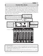
Страница 14: ... details refer to Normal mix mode on page 15 Character display section Following the FOSTEX VM88 display Init Mix will be displayed If the INPUT fader MAS TER fader is manipulated in this state will be lit behind the Init Mix dis play Refer to next page MASTER fader section The MASTER fader position is in dicated by numbers 00 99 The initial setting is 00 which is the initial mix setting The fader...

Страница 15: ...e can be adjusted by the top panel PHONES GAIN knob Throughout these operation the VM88 LCD display will change as explained below Character display section lights following the Init Mix display This symbol means edit and indicates that the setting had been changed from the initial state At this point of operation the initial state had been changed by this moving the INPUT and MASTER faders The MA...

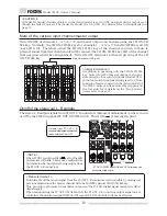
Страница 16: ...t and the S P DIF digital signal except the ADAT digital signal When manipulating the ST OUT ON OFF switch the ST OUT L R connector output signal only is controlled the monitor output DIGITAL OUT signal S P DIF or ADAT will not be affected NOTE When ST OUT is switched OFF all of the LED level meters will blink This is not a malfunction but indicates that no signal is being output from the ST OUT L...

Страница 17: ...ecause the fader setting before switching off power is in memory and the VM88 is indicating that fader and level adjustment is possible The fader position can be reset to the position prior to switching off power and the level position can be deliberately set to the present sound volume setting To return to the setting before switching off power Press the flashing FADER ADJUST key It will enter th...

Страница 18: ...tion only as a slave machine to the VM88 use the VM88 as the master machine and set its system clock to INT for the purpose of synchronizing the digital recorder with the VM88 digital output Otherwise use the VM88 as the slave and set the system clock to the initial state setting of EXT When selecting channels 5 6 or 7 8 for input channels of digital in be careful when setting the input modes of c...

Страница 19: ...S P DIF the digital mix signal will be output from the DIGITAL OUT connector without being affect by the ST OUT ON OFF switch However the signal of a channel whose mute is switched ON will not be output Please remember the DIGITAL IN status display function The DIGITAL IN status indication DIGITAL 44 1kHz 48kHz in the display will light or blink when the VM88 is in the status shown below 48kHz 44 ...

Страница 20: ...state and the channel to be edited is se lected by pressing each re spective CH ON CH SEL key The CH ON CH SEL key LED green of the se lected channel will blink Setup is changed by utilizing the DATA encoder Useful Information When selecting a desired item each time the respective key is pressed it will move to the next item and if the key is held down it will change one item backward in the setup...

Страница 21: ... 5 6 and 7 8 are selected the two channels will be simultaneously equalized If MASTER is selected both L and R will be equal ized at the same time Setup method of the EFFECT SEND level In the following the effects send level of the signal in the channel to which effects is to be applied is adjusted before sending it to the DSP multi effects EFF 1 EFF 2 contained in the VM88 It is also possible for...

Страница 22: ...l level output from the VM88 rear panel AUX SEND jack 1 2 The adjusted signal is sent to external equipment external effects and monitor amplifier from the AUX SEND jack The same as with the EFFECT SEND signal either POST or PRE can be selected for the AUX SEND signal The VM88 is set to POST in the initial state To change the setting please see below Setup of PRE POST 1 Light up the A1 or A2 dots ...

Страница 23: ...he POST setting no signal can be sent if the INPUT fader is at MIN 1 While pressing the EXIT key press the EFF AUX key to light up E1 E2 A1 or A2 in the status display section The LCD will display the following Example The character display section with E1 is lit 1 E1 Post is displayed Now channel 1 EFFECT SEND 1 PRE POST can be setup This indicates that the present EFFECT SEND 1 PRE POST is set a...

Страница 24: ...the most efficient way in order to eliminate harmful reverb elements and roughness This makes it possible to establish high density and transparent sounds Before the partical operation we will briefly discuss the effect functions here such as Reverb Delay Chorus and Flanger which are integrated in the VM88 The so called Reverb effect consists of various reflec tion sounds mixed together For exampl...

Страница 25: ... DigiPLATE REVERB Plate reverb that emphasizes a digital character with metallic early reflections 19 NormVOCAL REVERB All purpose hall reverb with no early reflections and uniform decay at all frequencies 20 PresVOCAL REVERB Short reverberation with extended high frequency is added to the early reflections of an ideal vocal booth Since this adds sparkle to the sound it is effective when you wish ...

Страница 26: ...he effect type for EFF 1 Press this to set the effect type for EFF 2 As described earlier in Normal mix mode raise the INPUT fader of a channel to which a signal is being input and raise the MASTER fader so that the sound is heard at an appropriate level As described earlier in Setting the effect send level raise the EFF 1 SEND level or the EFF 2 SEND level for the channel s to which you wish to a...

Страница 27: ... 2 key If you hold down the key for a certain length of time the parameter display will go back to the previ ous screen Useful Information When the effect parameter being edited is Delay Time or BPM you can also use the ENTER key or a foot switch to make the setting by tapping as an alternative to using the DATA encoder In order to use the foot switch for tap input you need to make settings in the...

Страница 28: ... Adjust the tone of the delay sound Range L9 L1 H1 H9 is Filter Off L1 L9 LPF larger numbers will lower the cutoff frequency H1 H9 HPF larger numbers will raise the cutoff frequency BPM delay effect parameters parameter type BPM DELAY For effect types 31 and 32 of the preceding Effect type table the following four parameters can be adjusted 1 BPM Adjust the BPM Range 30 250 bpm 221 steps in units ...

Страница 29: ...ct parameters parameter type FLANGE For effect type 36 of the preceding Effect type table the following four parameters can be adjusted 1 RATE Adjust the speed of modulation Range 0 1 2 0 Hz 200 steps in 0 01 Hz units 2 DEPTH Adjust the depth of modulation Range 0 99 100 steps in increments of 1 3 MOD DELAY Adjust the modulation delay Range 0 200 201 steps in increments of 1 4 FEEDBACK Adjust the ...

Страница 30: ...TE If you select scene number 00 and attempt to store the display will indicate Read Only and the operation will be ignored 4 Use the DATA encoder and cursor keys EFF 1 key EFF 2 key to input the scene name A scene name of up to eight characters can be assigned using the following characters and symbols 5 When you have finished entering the scene name press the ENTER key Useful Information The sce...

Страница 31: ...s the ENTER key The Level Adjust operation will be executed This will cause the volumes to change to the current fader locations Fader adjust When the physical fader locations and the actual volumes do not match for example after a scene memory has been recalled you can use this function to manually adjust the fader loca tions NOTE Fader Adjust will function in Normal Mix mode as well as after a s...

Страница 32: ...ul Information Scene direct recall can also be performed using a separately sold foot switch If you connect an unlatch type foot switch e g model 8051 to the FOOT SW jack you can use the foot switch to perform the procedure described above When you press the foot switch you will enter scene direct recall mode and pressing the foot switch again will step through the scene numbers If you hold down t...

Страница 33: ...em 3 Press the ENTER key The currently selected item will blink in the display Setting the various setup menus can be carried out in the same manner as shown below However the internal battery check menu only is for confirmation of the voltage display Blinking 4 Use the DATA encoder to select the desired setting For details on the available settings refer to the following page 5 Press the ENTER ke...

Страница 34: ... will be active Display Select item INT EXT The VM88 operates by its internal clock FS 44 1kHz The VM88 operates in sync with external digital signals Function DIGITAL IN setup menu DIGITAL IN format and the DIGITAL IN initiating channel can be set via the DIGITAL IN setup menu Setup content will be held even if the main power is switched off Display Select item OFF ADAT 44 1 DIGI IN setup not fun...

Страница 35: ...Phantom power 48V is supplied to INPUT 1 4 Top panel PHANTOM LED will be lit Function Phantom power 48V will not be supplied Top panel PHANTOM LED will be extinguished Please remember the following points when using the phantom power supply Do the following before using the phantom power When connecting a condenser microphone to MIC INPUT 1 4 XLR 3 31 type of the VM88 be sure this microphone requi...

Страница 36: ...unction Manipulation of the INPUT fader MASTER fader will affect the sound volume Input mode setup menu for Input 5 6 The input mode of INPUT 5 and 6 can be set The setup content will be held even if the main power is switched off Display Select item STEREO In 5 Mono INPUT 5 and 6 will enter the stereo input mode and thus separate signals can be input to channels 5 and 6 This is convenient for inp...

Страница 37: ... scene is recalled setup figure of the MASTER fader position will not be called and the fader position immediately prior to recalling the scene will be emploiyed directly This is convenient for live performances where you do not wish to recall only the output level but would like to set it at the performance site In all modes including the stored scene the MASTER fader will function normally regar...

Страница 38: ...ual Specific clamper As of December 1999 the Roland Model APC 33 is the most suitable Location for installing the clamper Battery check menu This lets you check the voltage of the internal battery After selecting this menu item press the ENTER key The voltage of the internal battery will be displayed allowing you to check it When you have checked the voltage press the EXIT key to exit Setup mode T...

Страница 39: ...2 Connector ø6mm phone jack Unbalanced Output level 10dBV Load impedance 10kΩ or more MON OUT L R Connector ø6mm phone jack Unbalanced Output level 10dBV Load impedance 10kΩ or more 0dBu 0 775Vrms 0dBV 1 0Vrms XLR connector pin assign 1 GND 2 HOT 3 COLD TRS jack pin assign T HOT R COLD S GND INSERT connector T SEND R RETURN S GND PHONES OUT Connector ø6mm stereo phone jack Load impedance 8Ω or mor...

Страница 40: ...ltage range The Affect of Immunity on This Equipment The affect of the European specification EN50082 1 coexistence of electromagnetic waves common immunity specification on this equipment are as shown below In the electrical fast transient burst requirements radiated electromagnetic field requirements and static electricity discharging environment this could be affected by generation of noise in ...

Отзывы: