


Configuring the FortiGate for the Network
NAT/Route mode installation
FortiGate-5000 series Installation Guide
01-28011-0259-20060210
25
4
Confirm the configuration settings, and then select Finish and Close.
You are now finished the initial configuration of the FortiGate-5000 module.
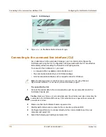
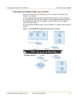
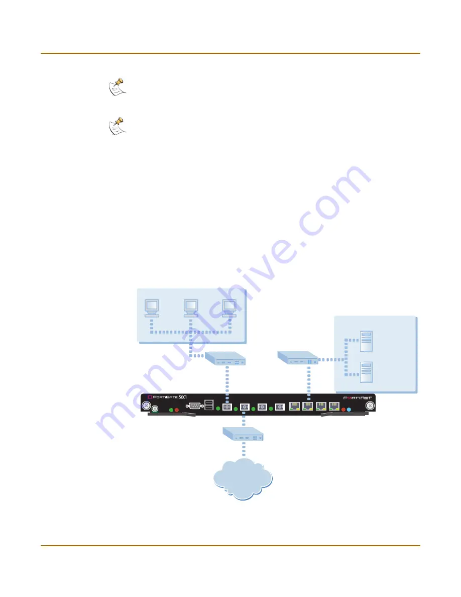
Connecting the FortiGate unit to the network(s)
After you complete the initial configuration, you can connect the FortiGate-5000
module between the internal network and the Internet.
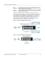
For the FortiGate-5001SX module and the FortiGate-5001FA2, connect interfaces 1
to 4 to gigabit fiber-optic ethernet networks or copper networks depending on the SPF
connectors that you have purchased. Connect interfaces 5 to 8 to gigabit copper
ethernet networks.
For the FortiGate-5002FB2 module, connect interfaces 1-6 to gigabit copper ethernet
networks.
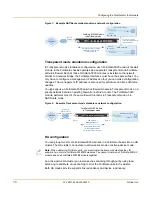
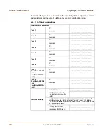
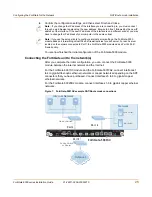
Figure 7: FortiGate-5001SX example NAT/Route mode connections
Note:
If you change the IP address of the interface you are connecting to, you must connect
through a web browser again using the new address. Browse to https:// followed by the new IP
address of the interface. If the new IP address of the interface is on a different subnet, you may
have to change the IP address of your computer to the same subnet.
Note:
If you use the setup wizard to configure internal server settings, the FortiGate-5000
module adds port forwarding virtual IPs and firewall policies for each server. For each server
located on the network connected to Port 1 the FortiGate-5000 module adds a Port2->Port1
firewall policy.
PWR ACC
STA IPM
CONSOLE
USB
1
2
3
4
5
6
7
8
Internet
Port 2
FortiGate-5001SX
Port 6
Network
Mail Server
Web Server
Public Switch
or Router
Port 1
Internal Network
Hub or Switch


