background image

Shelf manager CLI commands

Using the shelf manager CLI

FortiGate-5140B Chassis Guide

48

01-500-156415-20151104

http://docs.fortinet.com/


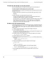
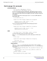
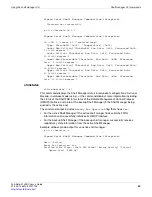
Upper Non-Critical Threshold, Raw Data: 0xa9 Processed data: 

1.656200 Volts

Upper Critical Threshold, Raw Data: 0xae Processed data: 

1.705200 Volts

Upper Non-Recoverable Threshold, Raw Data: 0xb3 Processed 

data: 1.754200 Volts

90: LUN: 0, Sensor # 5 ("CPU2 Voltage")

Type: Threshold (0x01), "Voltage" (0x02)

Lower Non-Critical Threshold, Raw Data: 0x6c Processed data: 

1.058400 Volts

Lower Critical Threshold, Raw Data: 0x67 Processed data: 

1.009400 Volts

Lower Non-Recoverable Threshold, Raw Data: 0x61 Processed 

data: 0.950600 Volts

Upper Non-Critical Threshold, Raw Data: 0xa9 Processed data: 

1.656200 Volts

Upper Critical Threshold, Raw Data: 0xae Processed data: 

1.705200 Volts

Upper Non-Recoverable Threshold, Raw Data: 0xb3 Processed 

data: 1.754200 Volts

90: LUN: 0, Sensor # 6 ("+5.0V")

Type: Threshold (0x01), "Voltage" (0x02)

Lower Non-Critical Threshold, Raw Data: 0xbe Processed data: 

4.655000 Volts

Lower Critical Threshold, Raw Data: 0xb8 Processed data: 

4.508000 Volts

Lower Non-Recoverable Threshold, Raw Data: 0xb0 Processed 

data: 4.312000 Volts

Upper Non-Critical Threshold, Raw Data: 0xdb Processed data: 

5.365500 Volts

Upper Critical Threshold, Raw Data: 0xe1 Processed data: 

5.512500 Volts

Upper Non-Recoverable Threshold, Raw Data: 0xe9 Processed 

data: 5.708500 Volts

90: LUN: 0, Sensor # 7 ("+3.3V")

Type: Threshold (0x01), "Voltage" (0x02)

Lower Non-Critical Threshold, Raw Data: 0xc0 Processed data: 

3.110400 Volts

Lower Critical Threshold, Raw Data: 0xba Processed data: 

3.013200 Volts

Lower Non-Recoverable Threshold, Raw Data: 0xb4 Processed 

data: 2.916000 Volts

Upper Non-Critical Threshold, Raw Data: 0xd9 Processed data: 

3.515400 Volts

Upper Critical Threshold, Raw Data: 0xdf Processed data: 

3.612600 Volts

Upper Non-Recoverable Threshold, Raw Data: 0xe5 Processed 

data: 3.709800 Volts

90: LUN: 0, Sensor # 8 ("+2.5V CPU 1")

Type: Threshold (0x01), "Voltage" (0x02)

Содержание FortiGate-5140B

Страница 1: ...ate 5140B chassis The most recent versions of this and all FortiGate 5000 series documents are available from the FortiGate 5000 page of the Fortinet Technical Documentation web site http docs fortine...

Страница 2: ...orkstation If no such station is available you can provide some ESD protection by wearing an anti static wrist strap and attaching it to an available ESD connector such as the ESD sockets provided on...

Страница 3: ...0 series chassis shall be installed and connected to the common bonding network FortiGate 5000 series chassis are suitable for installation in the Central Office and NEC The battery returns of FortiGa...

Страница 4: ...Warnings and cautions...

Страница 5: ...guration 21 FortiGate 5140B chassis power level requirements 21 Connecting the FortiGate 5140B chassis to DC power and ground 22 Connecting a FortiGate 5140B PEM to DC power 23 Connecting the FortiGat...

Страница 6: ...anager firmware version 39 List all FRUs in the chassis 39 List all sensors on a FRU 39 List only sensors that are outside of established thresholds 39 Display sensor data for a FRU 39 Display the FRU...

Страница 7: ...1 Before you begin 71 Chassis Design Background 71 Alarm LEDs 72 Reading the SEL 72 Clearing SEL logs 73 Example IPMC log output 73 Example FRU log output 75 Example sensor log output 77 Sample sectio...

Страница 8: ...Contents FortiGate 5140B Chassis Guide 8 01 500 156415 20151104 http docs fortinet com...

Страница 9: ...rtiGate 10 gigabit ethernet interfaces If all 14 slots contain FortiGate 5001D boards the FortiGate 5140B chassis provides a total of 28 40 gigabit ethernet interfaces You can also install FortiSwitch...

Страница 10: ...in a single FortiGate 5140B chassis The FortiGate 5140B chassis requires 48V DC power If DC power is not available you can install a FortiGate 5053B power supply shelf and PSU 5000B power supplies pur...

Страница 11: ...te 5140B chassis back panel cable tray not shown Do not operate the FortiGate 5140B chassis with open slots on the front panel For optimum cooling performance and safety the chassis slots must contain...

Страница 12: ...alarms and provide telco alarm interfaces You can also install a secondary shelf manager as a backup for the primary one For more information about these components see FortiGate 5140B shelf managers...

Страница 13: ...is DC power system ATCA board Interfaces Function Power Used WDC Heat Dissipation BTU hr FortiGate 5001B Front Panel 10 Gbps Fabric 10 Gbps FortiOS network security Max 225 Ave 187 768 FortiGate 5001C...

Страница 14: ...is installed on the right The secondary shelf manager is optional Table 1 FortiGate 5140B chassis physical description Dimensions 22 63 x 19 x 22 6 in 57 5 x 48 3 x 57 4 cm H x W x D Shipping weight c...

Страница 15: ...gers Each shelf manager has two ethernet interfaces CH0 and CH1 Both channels connect to the chassis backplane When the Ethernet channel selector button is pushed in recessed CH0 connects to the backp...

Страница 16: ...fans as required When the chassis is first powered on all cooling fans run at full speed Once the shelf manager is up and running the shelf manager reduces cooling fan speeds to maintain an optimum te...

Страница 17: ...critical power faults The cable required to connect to the alarm interface is not supplied by Fortinet To monitor alarms you should connect to the telco alarm interface of the active shelf alarm pane...

Страница 18: ...from 3 3 V to 48 V for between 200 and 300 ms The acceptance voltage range is from 0 to 48 VDC continuous handles up to 60 VDC at a 50 duty cycle The current drawn by a reset input does not exceed 12...

Страница 19: ...when inserting an new air filter to prevent damage to the sensors To insert a new filter slide it along the guide rails at each side of the shelf until the filter contacts springs at the back of the c...

Страница 20: ...ake sure there is enough clearance for effective cooling air flow See Figure 7 on page 20 for the minimum clearance requirements The diagram also shows the cooling air flow through the chassis and the...

Страница 21: ...PEMs to a FortiGate 5053B power convertor shelf if purchased with your FortiGate 5140B chassis The double hole lugs to be connected to the FortiGate 5140B PEMs include rubber boots that should be ins...

Страница 22: ...40 VDC to 72 VDC The chassis ships with both PEMs installed The PEMs provide redundant DC power connections for the FortiGate 5140B chassis and distribute DC power to all chassis slots and components...

Страница 23: ...to connector until it stops The insertion length must approximate the stripped length of cable Insert connector in die and compress between the markings beginning near the tongue of the connector Usin...

Страница 24: ...both connectors on the PEM 4 Connect two black 48V power wires from the DC power source to the connectors on the FortiGate 5140B PEM labeled the connectors on the right side of the PEM using the doubl...

Страница 25: ...re 2 on page 11 The ground terminal provides two connectors to be used with a double holed lug such as Thomas Betts PN 256 30695 1225 This connector must be connected to a local ground connection You...

Страница 26: ...power supplies The power supply shelf can be connected to high line AC input 186 240VAC or low line AC input 100 185VAC When connected to high line AC input a single power supply can provide 2725W of...

Страница 27: ...cond power supply for redundancy If you want completely redundant power for the chassis you can connect a second FortiGate 5053B unit to the other FortiGate 5140B PEM and include one or two power supp...

Страница 28: ...RTN with attached Listed closed loop double hole lugs with insulating boot suitable for minimum AWG 6 copper wire such as Thomas Betts PN 256 30695 1225 A FortiGate 5053B power supply shelf containin...

Страница 29: ...washers to secure the connectors 12 Cover the connectors with rubber boots Figure 11 Connecting a FortiGate 5140B PEM to a FortiGate 5053B power supply shelf 13 Make sure the power wires are secured t...

Страница 30: ...e metal surface on the chassis or frame 2 Make sure that the shelf and ground wire are not energized 3 Connect the green ground wire from the location s ground terminal to the ground connector on the...

Страница 31: ...nt temperature of the rack environment may be greater than room ambient temperature Make sure the operating ambient temperature does not exceed the manufacturer s maximum rated ambient temperature Air...

Страница 32: ...B boards installed in a FortiGate 5140B chassis in slot 1 or slot 2 provide session aware load balancing for all of the FortiGate 5001B series boards installed in the chassis A FortiController 5103B b...

Страница 33: ...HA heartbeat communication between FortiGate 5000 series boards in HA clusters To install FortiSwitch 5000 series boards see the documentation supplied with the board You can find copies of all FortiG...

Страница 34: ...tform Management Bus IPMB which is implemented on two redundant physical buses The shelf manager CLI can be used to communicate with the intelligent management controllers of the shelf with boards and...

Страница 35: ...the shelf manager CLI To connect to the shelf manager CLI 1 Connect a standard CAT5 RJ 45 Ethernet cable to the shelf manager Console port 2 Connect the console cable supplied with your chassis to yo...

Страница 36: ...enter to add a blank password Resetting a lost shelf manager password In the shelf manager root account password becomes lost you can reset the password to its factory default using the password_rese...

Страница 37: ...fic CLIA commands For example use the following command display help for the shelf pwrreorder command clia help shelf pwrreorder Pigeon Point Shelf Manager Command Line Interpreter Change the order of...

Страница 38: ...installed in a slot with an AMC module this slot has two FRUs FRU 0 and FRU 1 For example a FortiGate 5001A board with an AMC module is installed in logical slot 4 then at IPMB address 88 there will...

Страница 39: ...address in dotted decimal notation For example clia setlanconfig 1 ip 192 168 0 2 Display the shelf manager firmware version clia version To display a complete list of all information enter version wi...

Страница 40: ...ager Command Line Interpreter Authentication Type Support 0x15 None MD5 Straight Password Key Authentication Type Enables Callback level 0x00 User level 0x15 None MD5 Straight Password Key Operator le...

Страница 41: ...fault gateway enter the following commands clia setlanconfig 1 3 x x x x clia setlanconfig 1 6 x x x x clia setlanconfig 1 12 x x x x Sensor types Access to monitored information such as temperatures...

Страница 42: ...nd executed successfully You can re activate this deactivated board with the following command clia activate 90 0 Pigeon Point Shelf Manager Command Line Interpreter Command issued via IPMB status 0 0...

Страница 43: ...ese controllers This command is different from most of the rest of the commands because its works with ATCA boards and takes as arguments physical slot numbers instead of IPM controller addresses and...

Страница 44: ...thout including the clia prefix exit quit exit quit If you start the CLI interactive mode by entering clia without any parameters you can enter exit or quit to exit interactive mode clia fans Pigeon P...

Страница 45: ...er 14 FRU 0 Entity 0xf1 0x60 Hot Swap State M4 Active Previous M3 Activation In Process Last State Change Cause Normal State Change 0x0 Device ID String SFRU Alarm Board 14 FRU 1 Entity 0xf2 0x60 Hot...

Страница 46: ...fic parameters for a channel Enter the following command to display the IP address associated with channel 1 clia getlanconfig 1 ip Pigeon Point Shelf Manager Command Line Interpreter IP Address 192 1...

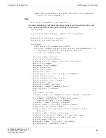
Страница 47: ...or number clia threshold IPMB address sensor name lun sensor number This command displays the current threshold values for the supported thresholds of the specified sensor s The sensor must be a thres...

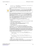
Страница 48: ...ts 90 LUN 0 Sensor 6 5 0V Type Threshold 0x01 Voltage 0x02 Lower Non Critical Threshold Raw Data 0xbe Processed data 4 655000 Volts Lower Critical Threshold Raw Data 0xb8 Processed data 4 508000 Volts...

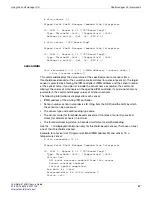
Страница 49: ...Non Critical Threshold Raw Data 0xde Processed data 2 708400 Volts Upper Critical Threshold Raw Data 0xe6 Processed data 2 806000 Volts Upper Non Recoverable Threshold Raw Data 0xee Processed data 2 9...

Страница 50: ...5 000000 degrees C 90 LUN 0 Sensor 14 CPU1 Temp Type Threshold 0x01 Temperature 0x01 90 LUN 0 Sensor 15 CPU2 Temp Type Threshold 0x01 Temperature 0x01 Display threshold sensor values for a specific se...

Страница 51: ...ion v turns on verbose output activate addr fru_id alarm alarm status action amcportstate v ipmc amc N fru_id board slot_number boardreset slot number busres force res busres info res busres lock res...

Страница 52: ...tthreshold addr f amc amc number help command ipmc v x addr localaddress minfanlevel addr fru_id min fan level minfanlevel min fan level poll quit sel clear addr number of items number of first item s...

Страница 53: ..._events deassertion_events setthreshold addr lun sensor_id sensor name unc uc unr lnc lc lnr r value shelf parameters shelf address_table shelf at shelf board_lan_cfg_params shelf cooling_state shelf...

Страница 54: ...terpreter Display the FRU Info of the dedicated FRU in the readable format instead of addr fru_id user may use power_supply N valid in 2 x systems only fan_tray N board N shm N to access the FRU on th...

Страница 55: ...he sensor that generated the event Event reading type code 3 bytes of event data in raw and processed if available formats The command sel clear clears the SEL on the specified IPM Controller at IPMB...

Страница 56: ...ber is 0x88 0x0219 Event at Aug 6 10 39 54 2009 from 0x88 0 0 sensor 0xf1 1 event 0x6f asserted 0xA2 0x00 0x89 0x021A Event at Aug 6 10 39 55 2009 from 0x8c 0 0 sensor 0xf1 1 event 0x6f asserted 0xA2...

Страница 57: ...e values of all sensors on the specified IPM controller If you do not enter any parameters the command displays values of all known sensors The following information is displayed for each sensor IPMB...

Страница 58: ...is reserved If the LUN is omitted the command applies to the sensor with the specified sensor number on the lowest LUN For example if the command specifies sensor 3 without explicit LUN qualification...

Страница 59: ...d Data 90 000000 degrees C shmstatus clia shmstatus v This command displays the Shelf Manager status in redundant configurations Active or Backup In verbose mode using v the command displays more info...

Страница 60: ...ing as the backup shelf manager and the backup shelf manager to switch to running as the active shelf manager You can enter this command from the active or backup shelf manger When you enter the comma...

Страница 61: ...word This command adds a new RMCP user account to the shelf manager The command also sets the same maximum privilege level and channel access flags for all channels Where user_id is a valid user ID us...

Страница 62: ...r v to display enabled user accounts When you use the clia user v command to display user accounts entries for disabled user accounts include Disabled If you don t include v the command only displays...

Страница 63: ...ls or encounters a problem for example a temperature sensor exceeds its range This section describes how to configure the shelf manager to send traps when a chassis FRU changes its FRU state FRU state...

Страница 64: ...manager will be SNMP traps whose format is defined in the Platform Event Trap Format specification The example is for alert channel 1 which is the Eth0 interface of shelf manager number 1 The basic r...

Страница 65: ...o 1 enables alert actions 3 Delay PEF and delay alerts for 60 seconds after the system powers up clia setpefconfig startup_delay 60 clia setpefconfig alert_startup_delay 60 4 Add event filter entries...

Страница 66: ...for all events You could raise the alert levels to 10 to only receive traps for critical events Add filter entry 1 for the FortiSwitch board in logical slot 1 The filter entry uses filter configuratio...

Страница 67: ...e following steps show to enter a command to deactivate selected FRUs which will result in a trap being sent 1 Enter the following command to view the state of PEM 1 in a FortiGate 5000 series chassis...

Страница 68: ...Identifies the instance of the device that holds the sensor that generated the event Byte 29 Sensor Number Sensor number 9 is the hot swap sensor for PEM B clia sensor 20 9 20 LUN 0 Sensor 9 FRU 7 HO...

Страница 69: ...1 98 6f 01 01 01 04 45 54 fa fc b6 o ET 0070 41 50 11 dd 00 80 00 50 c2 3f f0 9a 00 4f 13 c8 AP P O 0080 c3 75 00 00 20 20 02 20 09 00 00 a6 14 07 00 00 u 0090 00 00 00 19 0a 40 00 00 00 00 80 53 01 7...

Страница 70: ...the vi editor to edit the snmp conf file Enter the command vi snmpd conf 3 Scroll down to the part of the file that is similar to the following First map public community name COMMUNITY into a securit...

Страница 71: ...lf manager and all ATCA boards have their own physical IPMC chip and are assigned an IPMC address Their unique address is assigned based on what chassis slot they are physically inserted into Addition...

Страница 72: ...s also have alarm LEDs So for example if a FAN goes into an alarm state the alarm LED located on the FAN turns to RED For information about shelf manager LEDs see FortiGate 5144C shelf managers on pag...

Страница 73: ...fy the shelf manager that it s getting too hot to which the shelf manager would then notify the fans in the system to speed up to help cool the board better at which point the sensor would deassert th...

Страница 74: ...mal State Change 0x0 Device ID String Telco Alarm 18 FRU 0 Entity 0xf1 0x60 Hot Swap State M4 Active Previous M3 Activation In Process Last State Change Cause Normal State Change 0x0 Device ID String...

Страница 75: ...vice ID 0x00 Hot Swap State M7 Communication Lost Previous M4 Active Last State Change Cause Unknown 0xf 94 Entity 0xa0 0x60 Maximum FRU device ID 0x00 Hot Swap State M7 Communication Lost Previous M5...

Страница 76: ...ation In Process Last State Change Cause Normal State Change 0x0 Device ID String SFRU Alarm Board 18 FRU 1 Entity 0xf2 0x60 Hot Swap State M4 Active Previous M3 Activation In Process Last State Chang...

Страница 77: ...0 Hot Swap State M4 Active Previous M3 Activation In Process Last State Change Cause Normal State Change 0x0 Device ID String FAN MODULE ce FRU 0 Entity 0x1e 0x60 Hot Swap State M4 Active Previous M3...

Страница 78: ...ved 0xd6 Belongs to entity 0xf1 96 FRU 0 14 LUN 0 Sensor 131 HS Shelf FRU Type Discrete 0x6f Hot Swap 0xf0 Belongs to entity 0xf2 96 FRU 1 14 LUN 0 Sensor 112 HS Telco Alarm Type Discrete 0x6f Hot Swa...

Страница 79: ...Sensor 131 HS Shelf FRU Type Discrete 0x6f Hot Swap 0xf0 Belongs to entity 0xf2 96 FRU 1 18 LUN 0 Sensor 112 HS Telco Alarm Type Discrete 0x6f Hot Swap 0xf0 Belongs to entity 0xf3 96 FRU 2 18 LUN 1 S...

Страница 80: ...0xf0 1 FRU 0 20 LUN 0 Sensor 133 SYSTEM EVENT Type Discrete 0x6f System Event 0x12 Belongs to entity 0xf0 1 FRU 0 20 LUN 0 Sensor 135 FT Oper Status Type Discrete 0x0b Management Subsystem Health 0x28...

Страница 81: ...ure pwr ch 1 Type Discrete 0x04 OEM reserved 0xd2 Belongs to entity 0x15 96 FRU 0 c0 LUN 0 Sensor 2 Failure pwr ch 2 Type Discrete 0x04 OEM reserved 0xd2 Belongs to entity 0x15 96 FRU 0 c0 LUN 0 Senso...

Страница 82: ...s to entity 0x15 96 FRU 0 c2 LUN 0 Sensor 1 Failure pwr ch 1 Type Discrete 0x04 OEM reserved 0xd2 Belongs to entity 0x15 96 FRU 0 c2 LUN 0 Sensor 2 Failure pwr ch 2 Type Discrete 0x04 OEM reserved 0xd...

Страница 83: ...0 Sensor 2 FAN ALARM Type Discrete 0x6f OEM reserved 0xd2 Belongs to entity 0x1e 96 FRU 0 c8 LUN 1 Sensor 0 FAN Temperature Type Threshold 0x01 Temperature 0x01 Belongs to entity 0x1e 96 FRU 0 ca LUN...

Страница 84: ...served 0xd5 Belongs to entity 0x1e 96 FRU 0 cc LUN 0 Sensor 136 FW Revision ISC Type Discrete 0x6f OEM reserved 0xd6 Belongs to entity 0x1e 96 FRU 0 cc LUN 0 Sensor 1 Fan RPM Type Threshold 0x01 Fan 0...

Страница 85: ...FRU 0 Sample sections of SEL Output Shows the active shelf manager moving from M0 to M4 state active and working 0x0285 Event at Jan 1 00 01 46 1970 from 0x20 0 0 sensor 0xf0 0 event 0x6f asserted Hot...

Страница 86: ...http docs fortinet com 0x0080 Event at Jan 1 00 25 25 1970 from 0x8e 0 0 sensor 0x01 12 event 0x1 asserted Upper Critical 0x09 0xFF 0xFF Shows the board in ATCA slot 4 has exceeded the CPU board temp...

Страница 87: ...es examples FAQs technical notes and more Visit the Fortinet Knowledge Base at http kb fortinet com Comments on Fortinet technical documentation Send information about any errors or omissions in this...

Страница 88: ...nters a binding written contract signed by Fortinet s General Counsel with a purchaser that expressly warrants that the identified product will perform according to certain expressly identified perfor...

Отзывы: