

LED Description
Package Contents
PORT 0
PORT 1
PORT 2
PORT 3
PORT 4
RESET
POWER
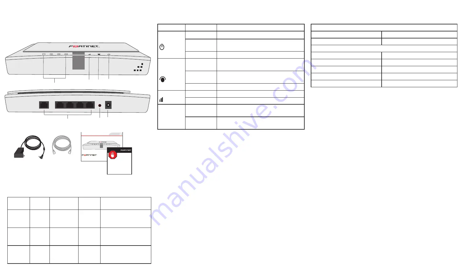
Port 1 to 4 LEDs
Wireless
LED
Port 0
LED
Power
LED
Ports 0 to 4
Reset
button
Power
button
Front
Back
Interface Description
Connecting
Administrator login
Username
admin
Password
<none>
Default port addresses
Port 0
192.168.1.2
Port 1
Do not use
Port 2
Do not use
Port 3
Do not use
Port 4
Do not use
Straight-through
Ethernet cable
FortiGate-30B
Copyright 2010 Fortinet Incorporated. All rights reserved.
Trademarks
Products mentioned in this document are trademarks.
QuickStart Guide
Power Supply
REGISTER
Factory Defaults
LED
State
Description
Power
Green
The unit is on.
Green Flash-
ing
The unit is starting up.
Off
The unit is off.
Ethernet
Port 0
Green
The correct cable is in use and Ethernet
connectivity is established.
Green Flash-
ing
The port is sending or receiving data
(activity)
Off
No link.
Wireless
Green
At least one wireless radio is enabled.
Off
Both wireless radios are disabled.
Port 1 to 4
Green
Port is connected. This condition is not
recommended.
Off
Port is not connected. This is the desired
state.
Inter-
face
Type
Speed
Proto-
col
Description
PORT 0 RJ-45
10/100
Base-T
Ethernet Use this port as the
primary connection to
the LAN
PORT 1
to PORT
4
RJ-45
10/100
Base-T
Ethernet Do not use these
ports.
Reset
button
Hold for 5 seconds to
reset the FortiAP unit
to its factory defaults.
Using the provided template and two M3 screws, attach the unit to the
wall or ceiling using the two mounting holes at the bottom of the FortiAP
unit. If placing on desktop, attach the rubber feet to the unit.
Connect the following to the FortiAP unit:
1. Insert a network cable to Port 0.
• Use straight-through cable for most equipment
• Use cross-over cable if connecting to FortiGate units without
auto MDI detect
2. Insert the other end of the network cable into your LAN Ethernet
edge switch, or directly to the FortiGate Controller.
3. Connect the power adaptor to AC outlet.
4. Insert the power adaptor connector to the FortiAP unit.
Note:
The FortiAP-220A does not support 802.3af POE therefore AC
power connection is mandatory. Use only the supplied power adaptor.
Substitution of power adaptor can damage the system and voids your
warranty.
Configuring
The FortiAP is designed to require no configuration in most networks.
Zero Configuration mode works if the FortiAP is directly connected to the
FortiGate performing the Wireless LAN Controller (WLC) functions, or
on the same layer-2 network and subnet as the FortiGate.
To enable the FortiAP using Zero Configuration:
1. Connect the network and power cable as described in the Connect-
ing section.
2. Once power is applied, the FortiAP goes through boot procedure
and requests an IP address from the DHCP server.
3. If the IP address is retrieved successfully, the FortiAP enters dis-
covery mode to locate a FortiGate wireless controller. The discovery
modes are:
• Broadcast
• Multicast
• DHCP option 138
4. If this is the first time connecting the FortiAP to the controller, only
the power light and Port 0 LED is lit. If the FortiAP has been pre-
provisioned in the controller, the Wireless LED is also lit.
5. Verify that the FortiAP has successfully connected to the controller.
In Web Config, go to
Wireless Controller > Physical AP > Managed
Physical AP
. Look for the name or serial number of the newly con-
nected unit.
6. In the Mode field, select
Enable
.
7. Select a FortiAP profile from the list and click OK.
8. The configuration is downloaded from the FortiGate unit to the For-
tiAP and the Wireless LED lights up.


