


Rev. 2.1
Getting started
Installing the stencil
1.
Loosen up the Y-axis alignment or stencil
2.
Unscrew the eight screws of the stencil frame
3.
Place the stencil in the first stencil holder
4.
Tighten the four screws.
5.
Do the same for the second stencil holder
6.
Tighten the stencil tensioner
Installing the first PCB
1.
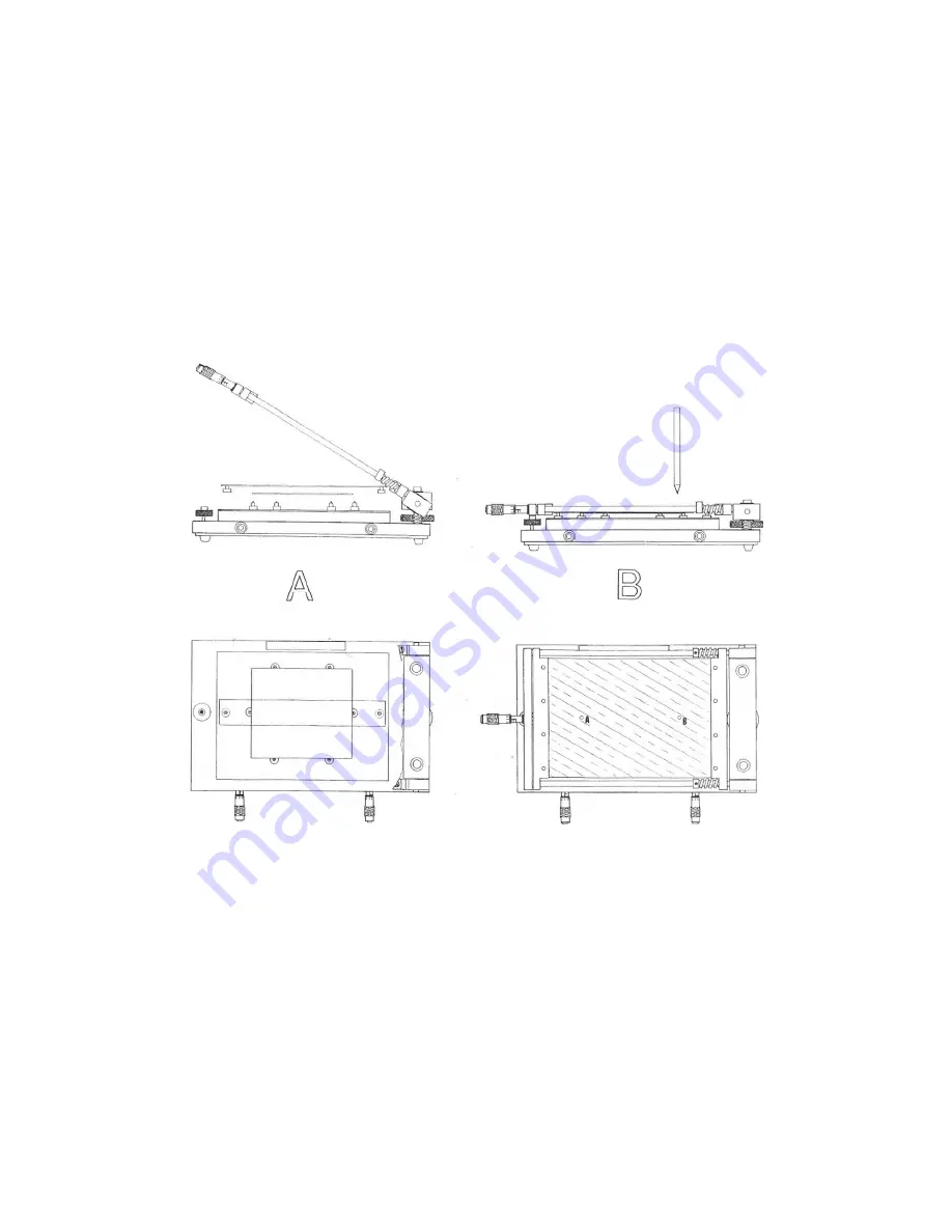
Open the printer. (picture A)
2.
Place the PCB roughly in its position with 4
3.
For large boards use the two magnetic points and place them in the middle of the PCB
4.
Place the transparent outline
5.
Find two easy to identify holes in the stencil which are
the marker pen to place a d
this open the printer. (picture A)
6.
Adjust the PCB until the PCB pads
7.
Remove the outline sheet without movi
8.
Use the bottom and top height controls to bring the stencil just above the PCB.
space between the stencil and PCB,
9.
Use the X- and Y-axis for small adjustments to align the stencil holes and PCB pads.
10.
Your printer is now ready for printing!
Manual stencil printer S1-01
axis alignment or stencil tensioner. (10)
t screws of the stencil frame. (A)
Place the stencil in the first stencil holder.
Do the same for the second stencil holder.
tensioner. (10)
(picture A)
Place the PCB roughly in its position with 4 to 6 magnetic placeholders.
use the two magnetic points and place them in the middle of the PCB
Place the transparent outline sheet over the PCB and close the printer. (picture B)
two easy to identify holes in the stencil which are on top of the outline sheet
dot on the outline sheet through the previously picked holes
ure A)
the PCB pads match the marker dots made during step 5.
without moving the PCB and close the printer. (picture B)
Use the bottom and top height controls to bring the stencil just above the PCB.
between the stencil and PCB, the better.
for small adjustments to align the stencil holes and PCB pads.
now ready for printing!
July 2019
use the two magnetic points and place them in the middle of the PCB.
(picture B)
sheet. Then use
sheet through the previously picked holes. After
(picture B)
Use the bottom and top height controls to bring the stencil just above the PCB. The less
for small adjustments to align the stencil holes and PCB pads.


