A0111-09-004 QUICK START GUIDE
Page 3
v1.00
Forsberg Services Limited
www.forsbergservices.co.uk
|
Company Registration No: SC104949, Registered Office: Forsberg Services Ltd, 1 East Craibstone Street, Aberdeen, LA1 4XF
15
COM1 TX-
GNSS COM1 (RS232 or
RS422)
Connector D-1 Pin 8
16
COM1 RXD / RX+
Connector D-1 Pin 3
17
COM1 RX-
Connector D-1 Pin 7
18
Power Return
Power
Connector F (Ring)
19
9-36V Power Input
Connector F (Tip)
Shield. Signal Ground
(E) un-terminated
Connector A , Shell
Connector B Pin 4
Connector C Pin 3
Connector D1 Pin 5
Connector D3 Pin 5
Connector D4 Pin 5
S
ETTING
U
P
Y
OUR
R
E
ACT+
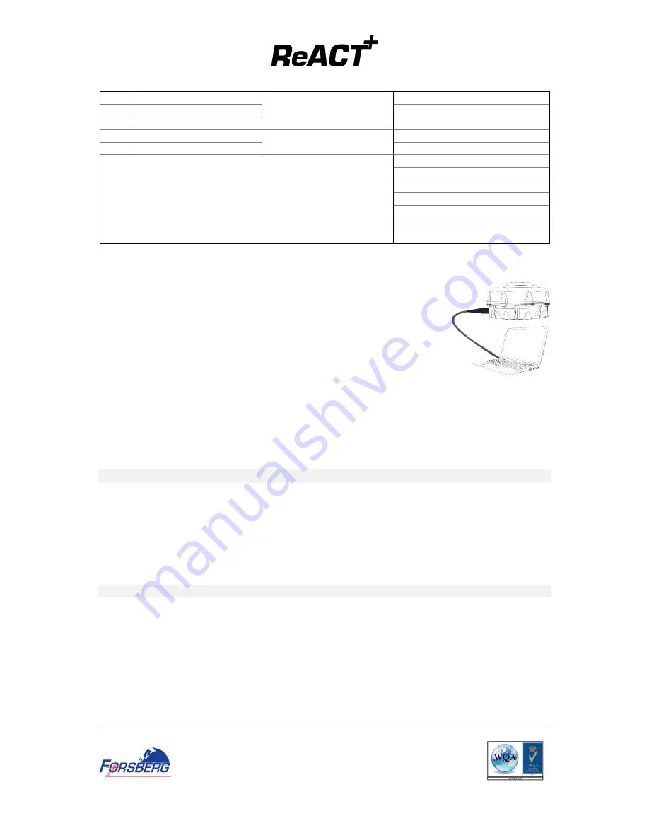
Complete the steps below to connect and power your ReACT+
1.
Connect the ReACT+ Comms cable to the ReACT+ Connector
2.
Mount the ReACT+ on a secure, stable structure with an unobstructed view
of the sky.
3.
Connect Connector D-1 (COM1) to the PC serial port DB-9 RS232 port.
4.
Connect the PWR connector to the 12VDC power source
5.
Turn on power to unit
C
ONNECTING TO THE
R
E
ACT+
Connecting to the ReACT+ can be done through FSL’s NAVpak software or through a serial terminal program,
such as RealTerm or HyperTerminal.
The default connections parameters are:
BAUD RATE: 9600
DATA BITS: 8
PARITY: NONE
STOP BITS: 1
FLOW CONTROL: NONE
C
HECKING THE
R
E
ACT+
P
OSITION IS
V
ALID
Once connected to the ReACT+ the BESTPOS message can be used to check the receiver position and position
quality.
To obtain the Position from the ReACT enter:
LOG BESTPOSA ONCE
This will return an ASCII message showing the Best Position from the receiver. For details of the message
please refer to: OEM7 Family Firmware Manual
Q
UICK
S
TART
C
ONFIGURING THE UNIT
The following commands will offer a reference for setting up the receiver, the full list are found in the OEM7
Family Firmware Manual.


