Extended Gazebo
Fixing Pack (BEXGAZFP)
Not to Scale
REQUIRED TOOLS :
(NOT SUPPLIED)
POZI DRIVE SCREWDRIVER
STEP LADDER
TAPE MEASURE
HAMMER
PARTS LIST
Important :
Assembly of this
Gazebo requires a
minimum of three
adults.
Must pre-drill for
each screw used.
IMPORTANT, RETAIN FOR FUTURE REFERENCE; READ
CAREFULLY
Check all parts prior to assembly
This building is pressure treated to ensure the longevity of
all timber components and to protect against rot. This may
leave a colour difference on some parts that will even out as
the moisture content stabilises. This will not require
additional treatment.
- Timber is a natural material. It will shrink and swell as a
result of varying moisture content.
- Due to the nature of the material the doors may need
some trimming for a neater fit.
- Please keep all plastic bags and small parts away from
children
- The roof of this building is not a load bearing structure.
- This product must be built on a solid level base.
Technical Help line:
0333 7777 089
8.30 am and 5.00
pm Monday to Friday.
In line with your statutory rights, please check all parts prior
to assembly, as assembly of damaged parts may be
deemed to be acceptance and this may affect the remedies
you are entitled to. If the product is not constructed in
accordance with the instructions, or is altered in anyway
(e.g. painted) the manufacturer cannot be held liable for any
resulting damage.
flush
E
BAGFINTOP Qty 2
BGLRFB2 Qty 6
(1296mm roof board)
GBSLAT830 Qty 4
(830mm bench slat)
J
GB
FB
RA
CE
Qt
y
4
(73
4m
m
be
nc
h f
ro
nt
br
ac
e)
GBSUP Qty 3
(885mm bench support)
EGBLEG440 Qty 4
(bench leg)
2
1
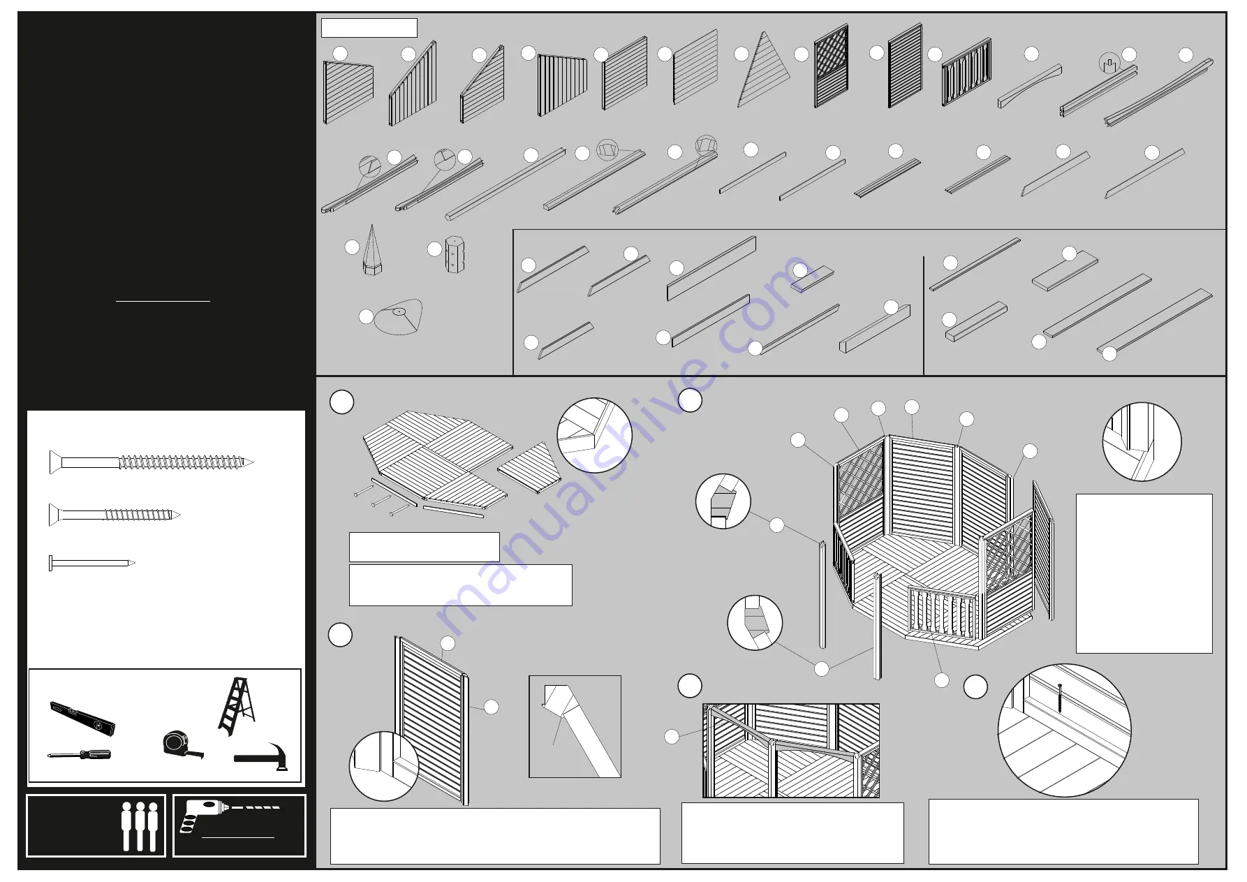
Place the floor sections
together to create the base
Position and fix each of the floor capping
pieces around the edge of the base using
3 x 30mm nails for each.
Fix the posts to either side of one of the panels and fix them to
each side using 4 x 70mm screws, screwing through the panel
framework first. Use 2 x 70mm screws for each side of the
baluster assembly.
flush
flush
Lip
Silicon Gun and Tube Qty 1
70mm screw Qty 132
45mm screw Qty 226
30mm Nails Qty 24
BAGRAF Qty 4
BAGFL1 Qty 1
EGFL1 Qty 1
EGFL2 Qty 1
EGPOSTRH Qty 2
EGSQFL Qty 2
EGRF Qty 2
BAGRF Qty 6
BABGMP Qty 2 BAGPP Qty 3
BAGBAL Qty 2 BAGARCH Qty 3
EGAPRAFC Qty 1
BAGFL2 Qty 1
EGRAFRHC Qty 2EGRAFLHC Qty 2
BAGPOST Qty 4
EGPOSTLH Qty 2
EGMETHAT Qty 2
EGFINBASE Qty 2
119181110NGPT Qty 2
(105x 1110mm board)
BAGFLCAP Qty 6
(64 x 1150mm strip
angled ends
)
EGFLCAP Qty 2
(64 x 1140mm strip)
119181110PT Qty 4
(119x 1110mm board)
GBSLAT1075 Qty 5
(
1075mm bench slat)
GBSLAT952 Qty 4
(952mm bench slat)
GBBRACE Qty 4
(1075mm bench back brace)
Square Bench Parts
GBSBRACE Qty 16
(330mm bench side brace)
BENCH ASSEMBLY PARTS
Angled Bench Parts
GBLEG440 Qty 16
(bench leg)
EGBRACE330 Qty 4
(330mm bench side brace)
BGLRFB1 Qty 6
(1224mm roof board)
EGSLAT1120 Qty 3
(120 x 1120mm bench brace)
EGBRACE1120 Qty 2
(102 x 1120mm bench brace)
EGBSUP Qty 1
(45 x 1120mm bench support)
A
B
C
D
E
F
G
H
I
J
K
L
M
N
O
P
Q
R
S
T
U
V
W
X
Y
Z
A1
B2
B3
B4
B5
B6
B7
B8
B9
B10
B11
B12
B13
P
H
I
R
R
Q
Q
J
P
5
3
K
top view
top view
4
Make sure that all of the
panels are secured to
posts and in line with the
outside of the base as
shown
(do not fix to the floor at
this point)
The R and Q posts must
be placed opposite
each other.
flush
Place the arch pieces between the posts
and so they are in line with the panels. Fix
the arch in place using 2 x 70 mm screws
for each using the pre-drilled holes.
Once all of the panels and arches are lined up and
secure, check that all of the sides are flush with the
base before securing each panel to the base using
4 x 70mm screws, screwing down through the
framing.
Issue 0115
B1
SPIRIT LEVEL


