


-19-
FES101E6
User Manual
FRu2r2_comport_a.cpp
FRu2r2_comport_a.h
//
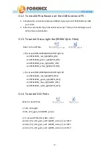
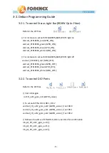
Retrieve the status of PINs DO-0, DO-1 and DO-2 for confirmation
int get_FR_u2r2_gpio_out0 ();
int get_FR_u2r2_gpio_out1 ();
int get_FR_u2r2_gpio_out2 ();
// To get value of PINs DI-0, DI-1, DI-2
int get_FR_u2r2_gpio_in0 (); // read DI-0
int get_FR_u2r2_gpio_in1 (); // read DI-1
int get_FR_u2r2_gpio_in2 (); // read DI-2
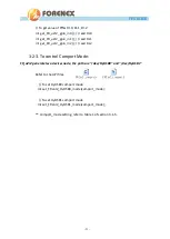
3-1-5.
To control Comport Mode:
FR_u2r2 generate two devices node, the path are “/dev/ttyUSB0” and “/dev/ttyUSB1”
.
Refer to the API files.
// To set ttyUSB0 comport mode
void set_FRu2r2_ttyUSB0_mode(comport_mode);
// To set ttyUSB1 comport mode
void set_FRu2r2_ttyUSB0_mode(comport_mode);
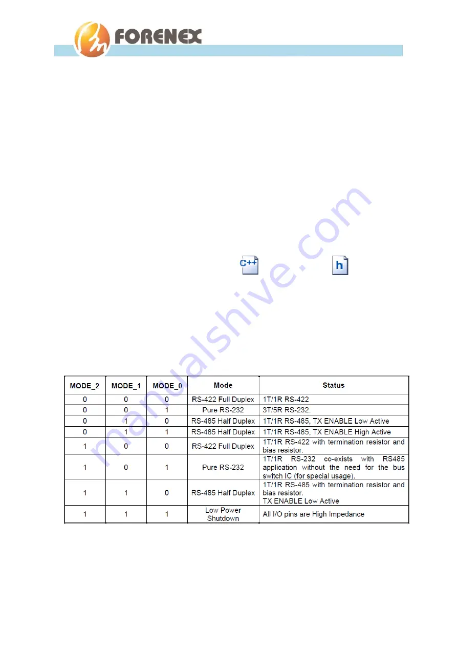
(Table 1)
Содержание FES101E6
Страница 4: ...4 FES101E6 User Manual 3 2 2 To control DIO Ports 20 3 2 3 To control Comport Mode 21...
Страница 9: ...9 FES101E6 User Manual 1 3 2 Panel Mounting Illustration 1 3 3 Clips Mounting Illustration...
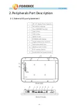
Страница 10: ...10 FES101E6 User Manual 2 Peripherals Port Description 2 1 External IO port placement...
Страница 17: ...17 FES101E6 User Manual Step5 Scroll to Settings USB Then Scroll to USB ADB HOST Set USB3 0 as ADB...


