14
4. USF Module Installation
USF Modules can be installed into any free slot if there are no installation slot limitations. Refer to the
"Installation Slots for Front and Rear Modules" in the USF-105AS Setup Guide for installation slot
limitation. When installing 12G-SDI supported modules (marked with *), install the supplied air duct unit
into Slot 5. If no 12G-SDI supported modules is installed, remove the air duct unit from Slot 5. Other
modules can be installed into Slot 5.
If multiple free slots exist, do not install modules side-by-side but leave slots open to prevent overheating
and facilitate signal connection from the rear panel.
NOTE
USF Modules come as front and rear sets. Be sure to install set modules into the same (front and
rear) slot locations.
Always install the rear module first, then the front module.
Install blank panels over free slots to prevent foreign material from entering and overheating the
chassis.
CAUTION
Beware of the occurrence of electrical breakdown in USF Modules.
Wear an antistatic wrist strap or equivalent material to equalize the electrical
potential of the USF-
105AS unit and the worker’s body. Do not touch the PCB
wiring or parts legs directly with your fingers while working.
Each USF Module can be installed and uninstalled while the power is on in
case of emergency. Shut down the power for non-emergency work.
When installing/uninstalling the front module while the power is on, the front
panel will be open state. The fans will stop during the procedure, so it is
essential to complete the installation within a short period and to close the front
panel immediately.
Be sure to shut down the power to install and uninstall a control module.
The procedure for installing the USF module in SLOT 1 is described below as an example.
4-1. Installing a USF Rear Module
1.
Open the front panel and shut down the USF-105AS power supply.
Refer to Sec. 3-2
. "Opening the Front Panel”.
2.
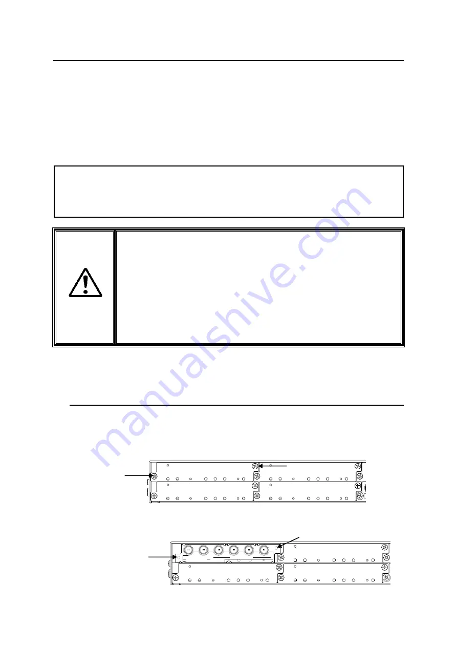
Slot 1 is the top slot in the left module block in the rear panel. Remove the blank panel by
detaching the two screws on both ends. Keep the blank panel and screws in a safe place after
removal.
3.
Insert the rear module into the slot and fasten both screws.
3G/HD/SD SDI IN
USF-1043FS
1
2
1
2
3
4
3G/HD/SD SDI OUT
Fasten
screw
Fasten screw
Loosen
screw
Loosen
screw


