


4
2. Installation / Replacement of MFR-41CPU
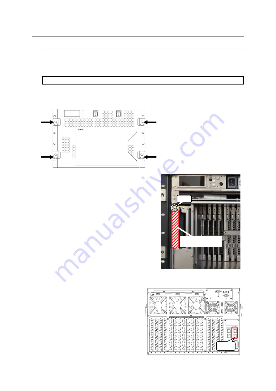
2-1. How to Install a New Card (if only one card installed)
This section describes how to install a new MFR-41CPU and change the CPU from a standalone
configuration to a redundant configuration.
IMPORTANT
Do not touch any components on the MFR-41CPU to protect it from electrostatic damage.
The following procedure shows how to install the CPU2 card (MFR-41CPU).
(1) Unfasten four fixing screws on the front panel and detach the front panel.
(2) Insert a new CPU card (MFR-41CPU) firmly
into its slot.
(3) Tighten the fixing screw on the CPU card
(MFR-41CPU).
(4) Re-install the front panel.
(5) Insert LAN cables into CPU2 MFR-LAN and PC-LAN ports and connect the cables with
respective hubs.
(6) If necessary, configure the network settings
for CPU2 and the settings for the number
of CPU operating days.
(See “Main Unit Settings” for network
settings and “Warning of CPU Consecutive
Operating Days/ Automatic Reboot” in the
MFR-4100/6100 Web Control Operation
Manual.)
The card installation is now complete.
MFR
ROUTING SWITCHER
MFR -4100
POWER 1
ON
OFF
OFF
ON
POWER 2
POWER
CPU1
CPU2
MFR-41CPU
installation slot
(3)
FAN 1
FAN 2
FAN 3
23 2C
SERIAL
422
ALARM
REF IN
FAN 4
FAN 5
CPU1
CPU2
M
F
R
-L
A
N
P
C
-L
A
N
P
C
-L
A
N
M
F
R
-L
A
N
A
C
1
0
0
-2
4
0
V
5
0
/6
0
H
z
IN
A
C
1
0
0
-2
4
0
V
5
0
/6
0
H
z
IN
2
1
INPUT
5
6
7
8
1
9
2
3
4
5
6
7
8
1
9
8
7
6
5
4
3
2
9
8
7
6
5
4
3
2
1
1
2
3
4
5
6
7
8
9
8
7
6
5
4
3
2
1
1
2
3
4
5
6
7
8
9
9
8
7
6
5
4
3
2
1
1
2
3
4
5
6
7
8
9
9
8
7
6
5
4
3
2
1
9
9
9
9
8
8
8
8
7
7
7
7
6
6
6
6
5
5
5
5
4
4
4
4
3
3
3
3
2
2
2
2
1
1
1
1
OUTPUT
INPUT
1
2
3
4
9
9
9
9
8
8
8
8
7
7
7
7
6
6
6
6
5
5
5
5
4
4
4
4
3
3
3
3
2
2
2
2
1
1
1
1
(5)


