

DSK-400
Quick Setup Guide
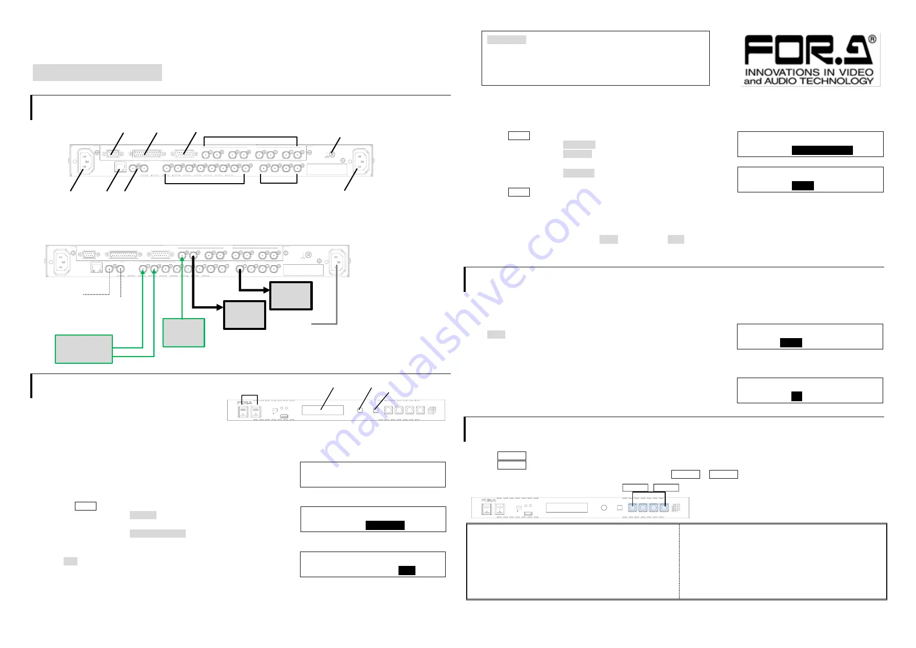
1. Connection and System Configuration
(1) Input SDI signals. (FILL, KEY, LINE IN)
(2) Connect to SDI signals output. (LINE OUT, AUX OUTPUT)
(3) Supply power to the DSK-400 using the supplied AC cord.
(4) Turn the power of the DSK-400 on using the front power switch.
2. Setup Procedure
Setting Menu Timeout Period
The DSK-400 automatically exits Menu display when no operation has been performed on the front panel
for 5 seconds
as default
setting.
Follow the procedure below to change Menu Timeout Period or turn off.
(1)
”HELLO! DSK-400” is displayed on Menu display when power is turned on.
30 seconds after, “SETUP MENU” is displayed and automatically switched to
the start-up display after 5 seconds.
(2) Press the MENU button to enter menu mode.
(3) Turn Menu control to select >PANEL and press Menu control.
(4) Turn Menu control to select MENU EXIT TIME and press Menu control.
(5) Turn Menu control to select timeout period.
When OFF is selected, Menu display is not automatically turned off.
(6) Press Menu control to confirm setting.
▶
See the operation manual Sec. 6-10-2.
“Menu Timeout Period.”
Setting System Video Format
System Video Format is not set in default setting so no video is output. Set the system video format following the procedure below.
(1) Press the MENU button to enter menu mode.
(2) Turn Menu control to select >SYSTEM and press Menu control.
(3) Turn Menu control to select FORMAT and press Menu control.
(4) Turn Menu control to select a video format and press Menu control to confirm.
(5) Turn Menu control to select >ASPECT and press Menu control.
(6) Turn Menu control to select an aspect ratio and press Menu control to confirm.
(7) Press the MENU button.
(8)
“Reboot Execution” will be displayed. Press Menu control to start reboot. Settings are reflected after the reboot.
▶
See the operation manual Sec. 6-1-
1. “System Video Format.”
Setting Date and Time
Open the [SYSTEM] menu. Set date under DATE and time under TIME.
▶
See the operation manual Sec. 6-1-9.
“Date and Time.”
3. Selecting Output Video
Selecting AUX output video
Key video of LINE1 input is output from AUX1 and LINE2 from AUX2 in default setting.
To change AUX1 output to PGM video, follow the procedure below.
Select AUX 1 under the [OUTPUT > OUT XPT] menu.
Select L1PG.
▶
See the operation manual Sec. 6-3-1.
“AUX Output Video.”
Assigning SUPER for LINE
SUPER1 is assigned to LINE1 and SUPER2 to LINE2 as default.
To display SUPER1 and SUPER 2 on LINE1, set as below.
Set SUPER2 to ON in the [OUTPUT > ASSIGN LINE1] menu.
▶
See the operation manual Sec. 6-3-3.
“Superimpose ON/OFF (LINE Outputs).”
4. Superimpose ON/OFF
Turning SUPER1 ON/OFF
Press the SUPER1 button to turn the light off. SUPER1 video will not be displayed.
Press the SUPER1 button to turn the light on. SUPER1 video will be displayed.
Turn ON/OFF SUPER2-4 video in the same way using the buttons SUPER2 to SUPER4.
Precautions
- Operate the unit
only
at the specified supply voltage.
-
Ensure
the unit is properly grounded at all times.
-
Ensure
the power cord and connectors are firmly connected.
-
Do not
access circuitry with power applied to the unit.
- Unit
should not
be operated or stored with the cover, panels,
and/or casing removed.
- Unit s
hould not
be operated or stored in a humid, dusty, etc.
environment. Doing so could result in fire or electrical shock.
-
Do not
allow fluids, metal fragments, or any other foreign
objects to enter the unit. If foreign matter does enter the unit,
turn the power off and disconnect the power cord immediately.
Remove the material or contact your authorized service
representative.
- If you notice any strange smells or noises coming from the
unit, turn the power off immediately, disconnect the power
cord, then contact your authorized service representative.
MODE: 2K((NONE) )
1:OFF 2:OFF 3:OFF 4:OFF
SETUP MENU > EXT I/F
8/9
> PANEL
PANEL
MENU EXIT TIME =
OFF
SYSTEM
FORMAT =
1080/59.94p
SYSTEM
ASPECT =
16:9
OUTPUT > OUT XPT
AUX1 =
L1PG
OUTPUT > ASSIGN LINE1
SUPER2 =
ON
http://www.for-a.com/
Packing list
DSK-400: 1
AC Cord: 1 set. EIA rack mount bracket set: 1 set
Conversion cable for connecting a DSK-RU: 1
CD-ROM: 1, Quick Setup Guide: 1 (This guide)
AC100-240V 50/60Hz IN
AC100-240V 50/60Hz IN
AUX OUTPUT
FILL/KEY
AUX4
AUX3
AUX2
AUX1
OUT4
IN4
OUT3
IN3
LINE
OUT2
IN2
OUT1
IN1
KEY3
FILL3
KEY2
FILL2
KEY1
FILL1
KEY4
FILL4
REMOTE
GPI IN / TALLY OUT
RS-422
GENLOCK
LAN
REF IN
2
1
RS-422
GPI IN/
TALLY OUT REMOTE IN1/OUT1 - IN4/OUT4
Ground terminal
AC IN
LAN
AC IN
AUX1-4
FILL1/KEY1 - FILL4/KEY4
REF IN
USB
DIGITAL SUPER KEYER
DSK-400
SUPER1
SUPER2
SUPER3
SUPER4
MENU
(PUSH)
OPERATE
LOCK
POWER ALARM
POWER 1
POWER 2
ON
OFF
POWER 1-2
Menu display
Menu control
MENU
Start-up display
USB
DIGITAL SUPER KEYER
DSK-400
SUPER1
SUPER2
SUPER3
SUPER4
MENU
(PUSH)
OPERATE
LOCK
POWER ALARM
POWER 1
POWER 2
ON
OFF
SUPER1 - SUPER4 buttons
AC100-240V 50/60Hz IN
AC100-240V 50/60Hz IN
AUX OUTPUT
FILL/KEY
AUX4
AUX3
AUX2
AUX1
OUT4
IN4
OUT3
IN3
LINE
OUT2
IN2
OUT1
IN1
KEY3
FILL3
KEY2
FILL2
KEY1
FILL1
KEY4
FILL4
REMOTE
GPI IN / TALLY OUT
RS-422
GENLOCK
LAN
REF IN
2
1
AC IN
Reference (BB or
Tri-level sync)
HD
Monitor
75
Ω
termination
HD
Monitor
Video
Recorder
Character
Generator
FILL
KEY
LINE