


6
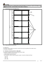
1.1 Load-bearing frame overall dimensions .................................................................................................................
9
1.2
Warning on modular generator configuration
.........................................................................................................
9
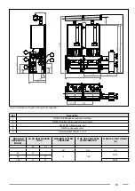
1.3
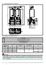
Direct left/right collector configuration
..................................................................................................................
10
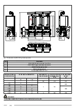
1.4
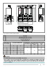
Left/right hydraulic separator configuration
..........................................................................................................
14
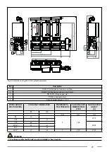
1.5
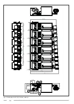
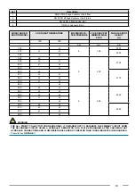
Left/right plate exchanger configuration
...............................................................................................................
22
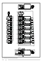
1.6 Positioning of generators on the frame ................................................................................................................
30
1.7
Assembling the hydraulic and gas components of the head module
...................................................................
31
1.8
Assembling the hydraulic and gas components of the expansion module
...........................................................
39
1.9
Operations to close flow and return taps
..............................................................................................................
48
1.10
Pump matching
....................................................................................................................................................
48
1.11
Assembling the hydraulic separator
.....................................................................................................................
49
1.12
Plate exchanger technical data
............................................................................................................................
51
1.13
Assembling the plate exchanger
..........................................................................................................................
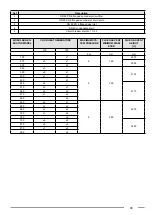
53
1.14
Flue gas collector assembly and configuration tables
..........................................................................................
59
1.15 Nominal data tables ..............................................................................................................................................
74
1.16 Nominal electrical data tables ..............................................................................................................................
76
1.17
Tables of dimensions, weights, connections and volumes
...................................................................................
77
1.18
Tables of flue - shared collector dimensioning
.....................................................................................................
80
1.19 Design data tables................................................................................................................................................
81
1.20 Pressure loss ........................................................................................................................................................
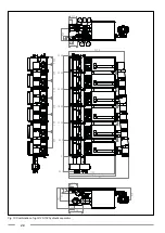
83
1.21 Wiring diagrams ...................................................................................................................................................
89
1.22 Cascade connections ...........................................................................................................................................
96
1.23
Decommissioning, disassembly and disposal
....................................................................................................
101


