


Installation
Before you begin
§
All dispensers must be installed level in both directions to ensure proper operation.
§
Service and ventilation clearances: 6" (15.3 cm) on right side of dispenser, 6" (15.3 cm) at top for ventilation and
12" (30.5 cm) at top recommended for service.
§
Countertop units installed without legs provide the option of taking utilities out bottom or back of dispenser (on
wall mount units and countertop units with legs, utilities exit from back). See counter cutout drawings for bottom
exiting utilities. For installations where utilities exit through back of dispenser, refer to back view drawings.
§
Counter depth must allow front of sink to be a minimum of 30.00" (76.2 cm) from wall.
Installing countertop dispensers without
legs
1. Position dispenser in desired location, mark
dispenser outline on counter and remove
dispenser.
2. Regardless of whether utilities will exit
through back or bottom of dispenser,
drill four 7/16" holes in counter to anchor
dispenser to counter
(Fig. 1).
3. For utilities exiting through bottom only:
(a) Make cut out
(Fig. 1).
(b) Move drain fitting from back of dispenser and
mount
(Fig. 2).
(c) Cut drain tube to length and attach to barbed
connection.
(d) Move inlet water fitting from back of
dispenser and mount
(Fig. 2).
(e) Cut water tubing to length and re-insert into
water fitting.
4. For all units: Apply a thick bead
approximately 1/4" (7 mm) diameter of
NSF-listed silicone sealant (Dow Corning
RTV-732
®
or equivalent) 1/4" (7 mm) inside
marked outline of dispenser.
5. Carefully lower dispenser on counter in
proper position and secure to counter with
four (4) 3/8"-16UNC bolts.
6. Smooth excess sealant around outside of
dispenser.
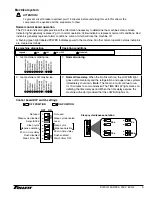
Fig. 1
2.00"
(5.1 cm)
12.00"
(30.5 cm)
14.37"
(36.5 cm)
4X
Ø.437"
(11 mm)
hole
1.04"
(2.6 cm)
16.00"
(40.7 cm)
Cutout
connections
through
bottom
12.00"
(30.5 cm)
0.81"
(2.1 cm)
16.00"
(40.7 cm)
1.50"
(3.8 cm)
17.87"
(45.4 cm)
5.62"
(14.3 cm)
Fig. 2 - Bottom exiting utilities (countertop units)
bracket
inlet
fitting
drain
fitting
drain tube
E12CI414A R290, 230 V 50 Hz 5
Содержание Symphony Plus 12 Series
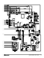
Страница 10: ...Wiring diagram 230 V 50 Hz 10 E12CI414A R290 230 V 50 Hz ...
Страница 11: ...E12CI414A R290 230 V 50 Hz 11 ...
Страница 14: ...14 E12CI414A R290 230 V 50 Hz ...
Страница 15: ...E12CI414A R290 230 V 50 Hz 15 ...