


7
INSTALLATION GUIDE
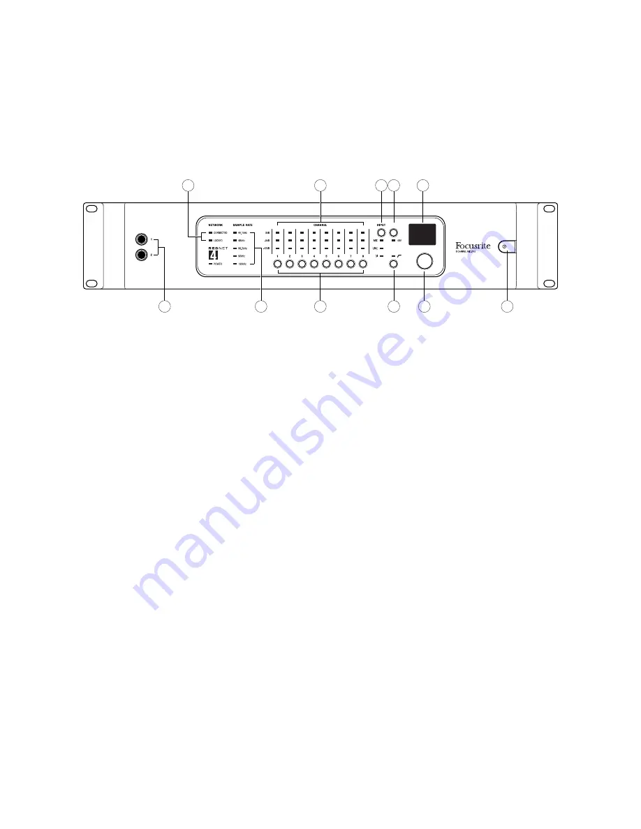
Unit connections and features
RedNet 4 - Front Panel
1
5
3
4
11
6
2
7
10
8
9
1. AC Power switch
2. Individual LEDs indicating signal level at each analogue input:
• Green – signal level above -42 dBFS
• Yellow – signal level above -6 dBFS
• Red – signal level has reached 0 dBFS
3. NETWORK status flags – two green LEDs confirming network status:
• CONNECTED – illuminates when the unit is connected to an active Ethernet network
• LOCKED – illuminates when a valid clock sync is received via the network
4. SAMPLE RATE indication – five yellow LEDs; only one of these (44 .1 kHz, 48 kHz, 88 .2 kHz,
96 kHz, 192 kHz) will be lit at a time, to confirm the sample rate that the system is running at.
5. CHANNEL 1 – 8 select buttons – these push-buttons select the input channel whose settings
are to be adjusted with the controls [6], [7], [8] and [9] described below. These settings can
also be controlled from RedNet Control. The channel selected is confirmed on the OLED [10].
Note that it also possible to link pairs of channels (1 & 2, 3 & 4, etc.) from RedNet Control,
to facilitate the use of stereo sources. The two channels may have different gains if wished
(useful if using MS mics), in which case the OLED displays the gain offset.
6. INPUT – this button scrolls through the input options for each channel – MIC, LINE or DI
(Inputs 1 and 2 only). A yellow LED indicates the input selected.
7. 48V – this button enables 48 V phantom power at the microphone input for the selected
channel.
Содержание REDNET 2
Страница 1: ...User Guide www focusrite com FA0772 02 ...
Страница 16: ...16 ...


