Model 914-HDE User Manual
Focal Technologies Corporation
3-2
A Moog Inc. Company
Document Number: 914-0601-00 Rev. 4.0
System Overview
914-HDE systems are used as pairs (one remote and one console) to provide a transparent HD video and data
link over optical fiber(s). The installed optical transceivers determine the maximum optical link speed, fiber type,
number of fibers (1 or 2), and link distance. The card version sets the operational bandwidth, which is
independent from the optical data rate. The optical link uses a proprietary data protocol ensuring reliable
transmission with extremely low latency using highly efficient and dynamic bandwidth utilization.
Typically, the uplink (remote to console) and downlink (console to remote) are combined on a single fiber
–
multimode or singlemode (standard)
– with a passive optical coupler known as a wavelength division multiplexer
(WDM). Standard systems operate with 1310 nm uplink and 1550 nm downlink wavelengths. In larger systems,
multiple 914-HDE units may be combined on a single fiber using a coarse wavelength division multiplexer
(CWDM) to take advantage of the high bandwidth of optical fiber.
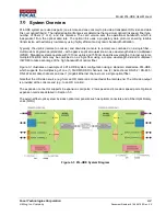
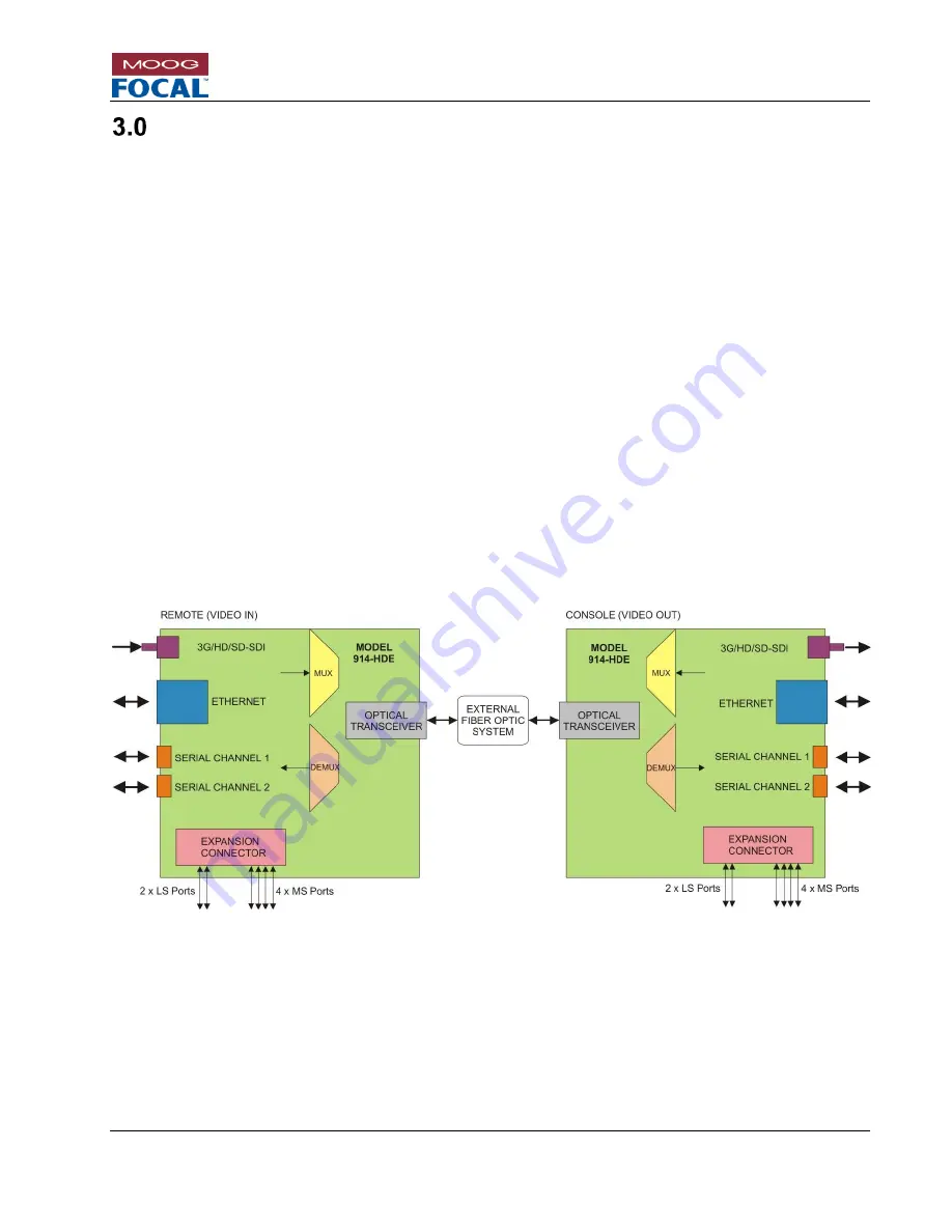
Figure 3-1 illustrates an example of a 914-HDE system configuration using a standard, standalone 914-HDE,
which supports the multiplexing of one (1) 3G/HD/SD-SDI channels, two (2) bidirectional RS-232 / RS-485 /
RS-422 serial data channels and one (1) Gigabit Ethernet channel over a single optical fiber.
Note that the HD video source (e.g. from an HD camera) is connected at the remote end. The HD video output
is provided at the console end (e.g. to an HD monitor).
The expansion connector supports 6 expansion card ports: 2 low speed and 4 medium speed ports. Optional
expansion cards are detailed in Section 5.0.
The external fiber optic system includes optical components such as optical connectors and a Fiber Optic Rotary
Joint (FORJ).
Figure 3-1: 914-HDE System Diagram


