FlyingBalsa MKII Humpback Скачать руководство пользователя страница 18

Radio Installation:

39) 

The rudder servo and connecting hardware is installed 

next. The servo mount is cut to fit a Hitec HS-85 servo. 
Simply install the rubber grommets and brass eyelets 
supplied with the servo and secure with the screws 
included with the servo. The plywood mount is already 
pilot drilled for the screws.  Install the EZ connector on 
the rudder horn making sure the set screw points DOWN. 
Bend a 1/4” leg on one end of the 1/16” wire rudder 
pushrod. Insert the bent end into the outer hole of the 
rudder servo arm and secure with the Du-Bro nylon 
keeper. Insert the other end of the rudder pushrod through 
the EZ connector on the rudder horn. With the servo 
centered at neutral and the rudder also secured in the 
neutral position, drill holes for the rudder horn making sure the center line of the EZ connector is directly over 
the rudder hinge line. Secure the rudder horn to the rudder. Travel adjustments will be covered in a later step.
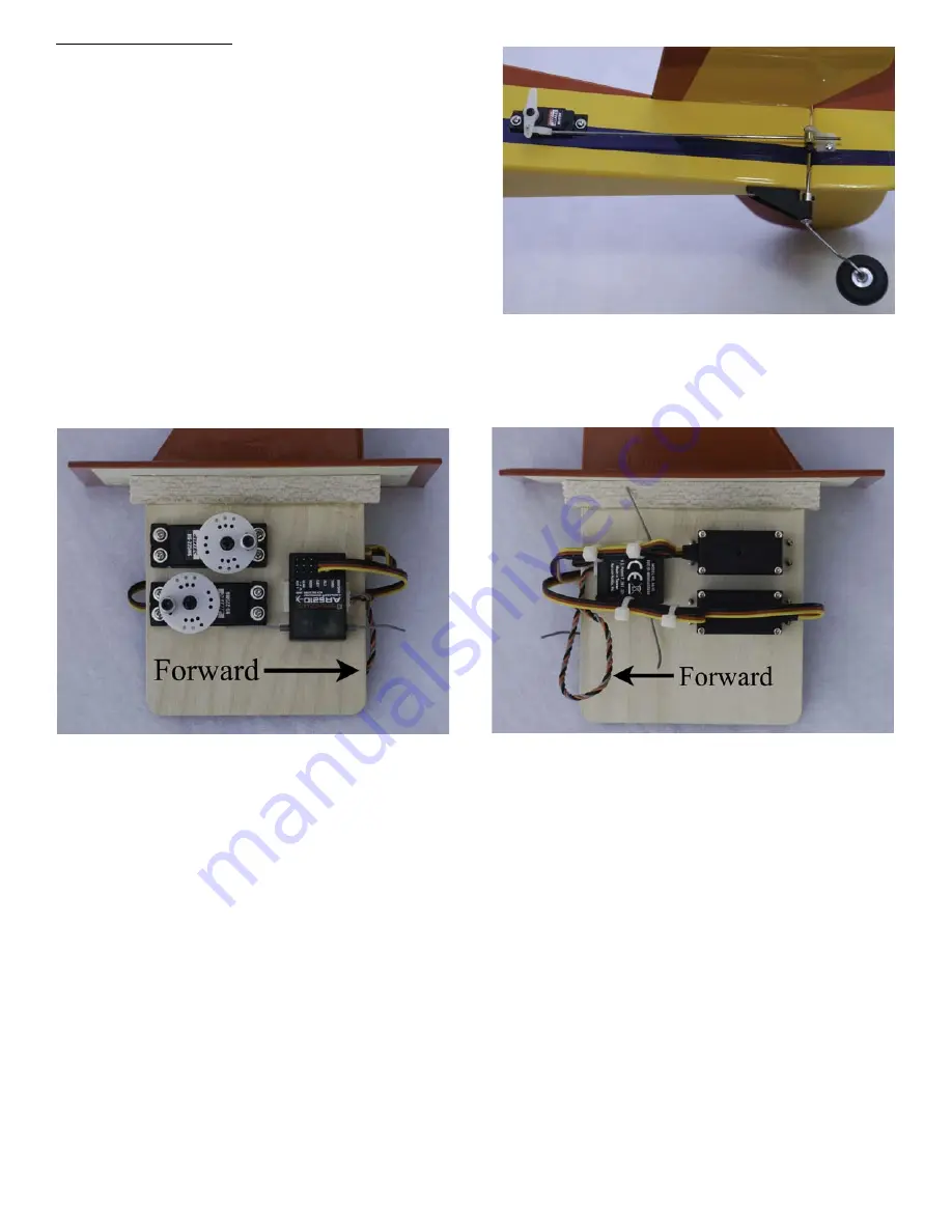
Figure 1

Figure 2

40) 

The pylon assembly is semi-self contained. There are only two connections external to the pylon assembly, 

the rudder servo and the ESC. The servo cutouts in the pylon core are sized and located for the recommended 
Hitec HS-225mg servos. If you decide to use servos other than HS-225mg's, you will need to make sure the 
linkage geometry is correct to prevent binding. The upper servo is for roll control and the lower servo is for 
pitch control. Simply install the rubber grommets and brass eyelets and then using the screws supplied with the 
servos, attach the servos to the pylon as shown in Figure 1 above. The holes are already pilot drilled for the 
screws.  The prototype used a Spektrum AR6210 receiver. Both the main and remote receivers are attached 
using double sided foam tape squares. Ensure both receivers are high enough on the pylon to clear the lower 
pylon support in the fuselage. Form loops in the excess servo lead wires are secure with small ty-wraps.  Figures 
1 and 2 above show how the prototype was done. Use the large round servo wheel that come with the servos. 
The smaller straight servo arms could possibly flex under flight loads. You will need to remove the servo wheel 
from the servo to install the EZ connectors. Use the center hole in the group of 3 servo wheel holes as shown in 
figure 1. The EZ connector shaft measures .092” so the holes in the servo wheel need to be reamed to fit the 
connector. Either a #42 or 3/32” drill bit will work. Insert the connector into the servo wheel and secure with the 
locking washer. An easy way to drive the washer onto the connector shaft is to use a small 1/4” drive “deep” 
socket 


and carefully hammer the lock washer onto the shaft. Go slow and carefully because this is a 'one time' 

try. The lock washer is not re-usable. Do not hammer the washer down so tight that the EZ connector will not 
rotate.  

16

Содержание MKII Humpback

Страница 1: ...very tight and performance is duplicated kit to kit We recommend seeking help from the local modelers in your area if you are inexperienced Orientation could be your toughest challenge We hope you enj...

Страница 2: ...tal stabilizer 4 Vertical stabilizer 4 Fuselage 5 6 7 8 9 10 11 Pylon 12 13 Tail installation 14 Tail wheel rudder main gear 15 Radio installation 16 Motor installation 17 Control surface rigging 17 R...

Страница 3: ...Doubler Doubler Fin Elevator Elevator Horizontal stabilizer Rudder Fuselage filler plug Battery Hatch Pylon Hatch F 2 F 1 Tongue Wire Trap Pylon Core Pylon Support Tail Wheel Mount Hatch Supports Pylo...

Страница 4: ...ws 3 4 40 x 3 4 socket head blade bolts 3 4 40 self locking nuts 3 nylon rotor blade bushings 3 4 flat washers for blade bolts 2 6 flat washers for main landing gear wire 2 5 32 wheel collars for main...

Страница 5: ...odelers tools we recommend the following Square for squaring formers and general usage 3 32 drill bit for reaming gimbal pivot hole 5 32 drill bit for drilling the landing gear torque blocks 29 drill...

Страница 6: ...urface Simply glue the elevators to the horizontal stabilizer as shown in this photo Use thin CA glue The elevators are fixed and do not move on this model Sand the horizontal tail assembly for film c...

Страница 7: ...lled on the left side Remove the servo filler plug from the tail card sheet and glue it into the servo cut out hole on the side you DO NOT want the servo to be on Use thin CA glue You will need to jus...

Страница 8: ...glue cures Note that it fits into the space formed where the plywood doublers end Align the firewall with the top of the fuselage sides It will extend slightly below the bottom of the fuselage and wil...

Страница 9: ...CA glue This piece will give support to the 1 8 balsa upper fuselage sheeting which will be installed in a later step Now the lower pylon support can be secured with thin CA glue 12 The 1 8 lite ply w...

Страница 10: ...4 Place the completed fuselage sub assembly on the line you drew on your building board Ensure that the small notch on the bottom of the firewall and formers F 1 and F 2 are directly over the drawn li...

Страница 11: ...at same hatch hole with a 18 drill bit for a clearance of the 8 32 nylon screw Reinstall the pylon hatch assembly and secure with a 8 32 nylon screw in the hole you just tapped Repeat the drill and ta...

Страница 12: ...arefully mark the two screw positions for the tank hatch It is recommended that you drill and tap each hole one at a time the same as was done for the pylon hatch Remove the hatch then drill and tap t...

Страница 13: ...accomplished using a 21 drill bit in a battery powered drill 24 Cut a hole for the motor wires approximately 1 2 in diameter just aft of the landing gear mount Also cut a battery cooling vent approxi...

Страница 14: ...ference mark on where to apply the epoxy glue The entire fork assembly can be done in one setting using 15 minute epoxy glue The holes for the 1 8 dowel fork pins are all pre drilled Apply epoxy to th...

Страница 15: ...ilm covering but you will need the special Monokote type of trim tool to accomplish this Another option would be to simply paint the inside surface of the forks Leave the bottom end of the pylon sides...

Страница 16: ...e fin and rudder 33 Test fit the horizontal stabilizer to the fuselage and carefully remove the film covering from the stabilizer bottom where it gets glued to the fuselage Glue the vertical fin to th...

Страница 17: ...he tail wheel wire into the rudder Insert the three rudder hinges into the slots of the rudder There is no easy way to accomplish the next step You will just have to work methodically and carefully in...

Страница 18: ...rect to prevent binding The upper servo is for roll control and the lower servo is for pitch control Simply install the rubber grommets and brass eyelets and then using the screws supplied with the se...

Страница 19: ...Re install the pitch and roll servo control wheels as shown in Figure 1 of step 39 Drill a 3 16 hole in the pylon hatch for the 4 40 pushrods as shown on the CAD drawings If you are using different se...

Страница 20: ...e and flush with the top and bottom of the blade TIP temporarily installing a blade bolt through the bushing is an excellent alignment aid for ensuring the bushing is square to the blade When satisfie...

Страница 21: ...Initial Radio Setup 46 This section outlines a basic setup procedure This will give you a basic starting point that can be fine tuned during your test flights 46 1 Throttle glow engine conversion rig...

Страница 22: ...takeoff run When you are at half power pull a very small amount of aft stick until the blades enter auto rotation and when the wheels are light pull a little more aft stick until airborne and add powe...

Страница 23: ...ort or parts flyingbalsa bellsouth net Yahoo groups support forum http groups yahoo com group ptgyrosupport FlyingBalsa LLC PO Box 1491 Collierville TN 38027 If you purchased your kit through a retail...

Отзывы: