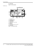
WS000510A
2 1 9 10
6
5
4 3
7,8
Pt100
MINI
C
A
S
II
19
20
21
22
23
24
11
12
MiniCAS
17 18 19 20
22 23 24 25 26 27 28 29 30 31 32
1 2 3 4 5 6 7 8 9
1 1 12
14
16
24 V
CONTROL AND STATUS
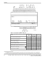
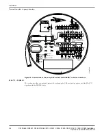
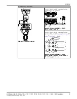
Figure 22: Connections at the CAS base unit
For more information about the CAS system, see
(page 26).
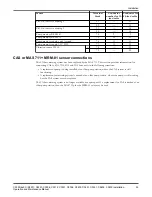
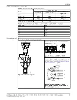
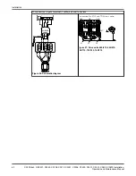
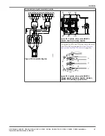
Connection table
This table shows how the conductors are connected to the different sensors.
Sensor
Terminal
block
Conductor number
for 12-lead cable
Conductor for 24-
lead cable
Float switch in the stator housing
1
1
1
2
2
2
Pt100 in the main bearing
3
3
3
4
4
4
Thermal switches or thermistors in the stator
5
5
5
6
6
6
Pt100 in the support bearing
37
7
7
38
8
8
Float switch in the junction box
9
9
9
10
10
10
CLS sensor in the oil housing
+
33
11
11
–
34
12
12
Pt100 in the stator winding 1
19
—
19
20
—
20
Pt100 in the stator winding 2
21
—
21
22
—
22
Pt100 in the stator winding 3
23
—
23
24
—
24
Cable charts
Electrical Hazard: The end of the cable must not be submerged. Leads have to be above flood level, as
water may penetrate through the cable into the junction box.
Installation
58
C3300/6x5, C/R3231, C3240, C3306, C3312, C3351, C3356, C3400, C3501, C3531, C3602, C3800 Installation,
Operation and Maintenance Manual
Содержание C/R3231
Страница 2: ...End of Disclaimer text ...
Страница 4: ......
Страница 170: ......
Страница 171: ......

