5
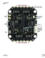
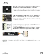
Motor Wires: To change the rotation direction you can use the [JP1] solder jumpers on
top of the board to match Mot1/CW, Mot2/CCW, Mot3/CW and Mot4/CCW.
So you can solder your wires straight to the motor pads and change the direction later
by closing the matching solder jumpers next to the motor outputs on top of the board.
Receiver input: Connect your 3-wire (S-Bus, Spektrum, PPM …) receiver signal port to
the “UPort”. The receiver’s telemetry wire goes to the “RC TLM” on top of the board.
Spektrum Sats can also be connected to the UPort but the 3,3V needs to be connected
to the 3,3V pad on the bottom side.
Expansion Port: Can be used for serial in/output (RX1 / TX1), e.g. logger or OSD, WiFi
connection and LED support. The 5V output can handle 1A max.
V-Lipo outputs the lipo power.
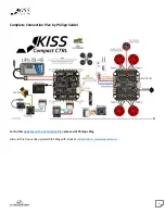
When using external devices make sure their current consumption doesn’t overload
the CC, especially for VTXs and LEDs. Use a Polulu stepdown or PDB 5/12V instead.
Lipo connector on the bottom: The GND and Lipo + on the bottom can be used to feed external devices.
ESC Telemetry: For the ESC telemetry the TX jumpers on the backside are already bridged. No need to solder them like
with the AIOv1.
Содержание KISS Series
Страница 3: ...3 Connections Wiring...
Страница 4: ...4...


