background image

Oblò backup system 2.0  

User’s manual

FLYBOX

Rev. 1.0

®

Important notices & warnings

NOTE: 

Keep this manual in the aircraft.This document

must accompany the device in the event of change of
ownership.

NOTE: 

This device is intended for installation onto non

type  certified  aircraft  only,  because  it  has  no  aviation
certifications. Refer to your local aviation authorities to
check if this device may be installed in your aircraft.

CAUTION:

 Read entirely this manual before installing

this device in your aircraft, and follow the installation and
operating instructions described here.

CAUTION: 

When  the  installation  is  finished  you  must

do  a  test,  prior  to  flight,  switching  on  all  the  possible
source of electric noise and   checking  the  properly
operation of this device.

WARNING: 

Responsibility  for  installation  lies  entirely

with  the  installer.  Responsibility  for  operations  lies
entirely with the operator.

IMPORTANT: 

If you do not agree with the notices above

do not install the device in your aircraft, but return the
product for a refund.

Microel  s.r.l.  reserves  the  right  to  change  or  improve  its
products. Information in this document is subject to changes
without notice.

Содержание Oblo backup system 2.0

Страница 1: ...Oblò backup system 2 0 Revision 1 0 07 11 2018 Flybox ...

Страница 2: ...Page intentionally left blank ...

Страница 3: ...MECHANICAL INSTALLATION SECTIONS ELECTRICAL INSTALLATION OPERATING INSTRUCTIONS TECHNICAL SPECIFICATIONS ...

Страница 4: ...fully satisfy you SYMBOLS USED IN THE MANUAL NOTE Used to highlight important informations CAUTION Used to warn the user and indicate a potentially hazardous situation or improper use of the product WARNING Used to indicate a dangerous situation that can cause personal injury or death if the instruction is disregarded ...

Страница 5: ...device in your aircraft and follow the installation and operating instructions described here CAUTION When the installation is finished you must do a test prior to flight switching on all the possible source of electric noise and checking the properly operation of this device WARNING Responsibility for installation lies entirely with the installer Responsibility for operations lies entirely with t...

Страница 6: ...7 1 2 Installation notices 8 SECTION 2 Electrical installation 2 1 Electrical installation 9 Ferrite mounting 10 SECTION 3 Operating instructions 3 1 Description and use of the device 12 3 2 Normal operating procedure 15 3 3 Endurance testing 16 3 4 Warning led notifications 17 SECTION 4 Technical specifications 18 Warranty 19 ...

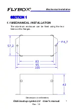
Страница 7: ...backup system 2 0 User s manual FLYBOX 7 Rev 1 0 Mechanical installation SECTION 1 1 1 MECHANICAL INSTALLATION The aluminum enclosure can be fixed using the two holes on the flanges Dimensions in millimeters ...

Страница 8: ... a Ni Mh battery pack with operating temperature range 0 45 C Outside of these limits the battery is not charged so you need to install it away from heat sources for example heater vents If possible choose an area where there is some air circulation Select an area that is accessibile to allow for future battery servicing ...

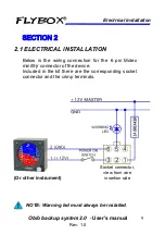
Страница 9: ...CAL INSTALLATION Below is the wiring connection for the 6 pin Molex minifit jr connector of the device Included in the kit there are the corresponding socket connector and the crimp terminals Socket connector view from wire insertion side Or other instrument NOTE Warning led must always be installed ...

Страница 10: ...e from pin 3 6 is always present the voltage of the internal battery Complete the wiring harness and connector installation prior to attaching the connecctor to the device This is essential to ensure the wires do not inadvertently short together during installation remember that the internal battery of the device is ready to deliver output power even when the aircraft electrical system is in the o...

Страница 11: ...ng engine start Connects directly to the power bus of the aircraft and provides at its output the supply voltage for connected instruments and simultaneously charge the internal battery pack Charging system The device continuously monitors the state of the internal battery and recharges it as necessary when the aircraft electric system is turned on The maximum input current for battery recharging ...

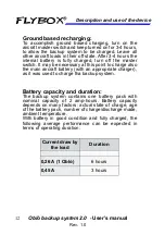
Страница 12: ...may be necessary at this point to charge also the main aircraft battery with an appropriate charger as it was used to charge tha backup system Battery capacity and duration The backup system contains one battery pack with nominal capacity of 2 amp hours Battery capacity depends on many factors actual state of charge age of the battery pack number of charge discharge made ambient temperature With b...

Страница 13: ...ou will notice continuous turn off turn on In this condition is essential to turn the instrument off to avoid further discharging of the battery and proceed with a charge as soon as possible Storage beyond 3 months If you are not using the aircraft or if you leave disconnected the backup system be sure to make a full charge as explained in the paragraph Ground based recharging at least once every ...

Страница 14: ...rating of the backup system and you can check that the internal battery is not fully discharged Turn on the aircraft master switch and ensure that equipments connected to the backup system remains energized Continue with the normal start up operating procedures Shut down procedure Shut down aircraft engine using normal procedures Shut down the aircraft master switch and verify that equipments conn...

Страница 15: ...urn off or it begin continuous turn off turn on If the equipment connected is not an Oblò Measure the time until the equipment no longer functions or the time until the output voltage of the backup system drops to 9 5 Volt Avoid voltage to fall below 9 5 Volt to not damage the battery pack 4 At the end of the test fully charge the battery by performing the procedure explained in chap 4 paragraph G...

Страница 16: ...se excessive charge time it means that the battery pack no longer holds a full charge so you need to replace it contact Microel srl to order a new battery pack 4 flashes followed by a pause battery temperature outside the operating limits 0 45 C in this case the charging system will inhibit the charge of the battery until the temperature falls within the operating limits above 0 or below 45 C 5 fl...

Страница 17: ...inifit jr connector included Operating temperature range 10 60 C Charge operating temperature of the internal battery pack 0 45 C Supply voltage 10 16 V Max continuous input current 1 A Max continuous output current 0 45 A Output voltage 10 12 V during backup operation Batteries Internal Ni Mh battery pack Weight 220 g 4 1 TECHNICAL SPECIFICATIONS SECTION 4 ...

Страница 18: ... person WARNING All photos data drawings instruments layouts technical solutions and data representation you find in this document or watching at FLYBOX instruments working and or you can access by means of any other media including web sites are sole property of MICROEL s r l cannot be copied or imitate without a written permission of MICROEL s r l itself and are protected by law even by means of...

Страница 19: ...Page intentionally left blank ...

Страница 20: ...MICROEL s r l Via Mortara 192 194 27038 Robbio PV ITALY Tel 39 0384 670602 Fax 39 0384 671830 www flyboxavionics it ...

Отзывы: