background image

Omnia57-80 CHRONO 

Installation and User Manual,

Safety Instructions and Warning Booklet

FLYBOX

Rev. 2.0

®

27

Operating Instructions

Note:

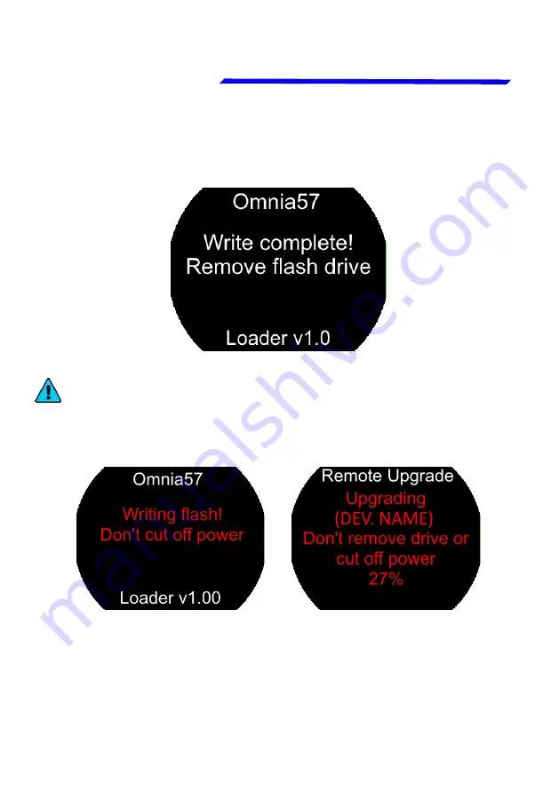
 if the USB stick is installed on a device other than

the  one  you  are  updating,  the  following  messages  will
appear on the 2 devices:

Wait until this message will appear and then remove the
USB stick. The instrument will reboot with the new software.

Device  is  being
Update

Remote 

device

where  the  USB  is
connected

Содержание CHRONO

Страница 1: ...Omnia57 80 CHRONO Installation and User Manual Safety Instructions and Warning Booklet FLYBOX Rev 2 0 1 CHRONO Omnia57 80 family Flybox ...

Страница 2: ... Warning Booklet This product is not TSO d and cannot be installed into traditional FAA Part 23 and similarly Type Certificate Aircraft Document A2021CHRONO Revision 2 0 04 2021 For firmware version 1 6 This booklet is suitable for printing in A5 format ...

Страница 3: ... INSTALLATION SECTIONS ELECTRICAL INSTALLATION OPERATING INSTRUCTIONS INSTRUMENT SETTINGS INTRODUCTION IMPORTANT NOTICE AND WARNINGS INDEX OMNIA FAMILY SYSTEM OVERVIEW TECHNICAL SPECIFICATIONS WARRANTY DISCLAIMER ...

Страница 4: ...Examples of available screens ...

Страница 5: ...eate a light and compact product powerful and easy to install and use The Omnia instrument family is equipped with a state of the art highly visible display a powerful 32 bit microcontroller and the latest generation of solid state sensors to ensure reliability and accuracy over time The owner has the possibility to keep the instrument software up to date by downloading the latest available revisi...

Страница 6: ...the Installation and User Manual Safety Instructions and Warning Booklet NOTE Used to highlight important information CAUTION Used to warn the user it indicates a potentially hazardous situation or improper use of the product WARNING Used to indicate a dangerous situation that can cause personal injury or death if the instruction is disregarded ...

Страница 7: ...ve explained and heed all instructions and warnings supplied with this product and with those products intended for use in association with it Always keep a copy of the Installation and User Manual Safety Instructions and Warning Booklet on the aircraft In case of change of ownership the Installation and User Manual Safety Instructions and Warning Booklet must be delivered together with all of the...

Страница 8: ...ho carried out such operation FAILURE TO DO SO MAY RESULT IN SERIOUS INJURY OR DEATH WARNING This device is operated through a software which from time to time can be updated and or subject to change Please always refer to the Installation and User Manual Safety Instructions and Warning Booklet for the last updated version of the software available at www flyboxavionics it WARNING Do NOT rely on t...

Страница 9: ...al updates For some products registration may be required to receive important news or information on available firmware updates or to receive security information NOTE Flybox Avionics reserves the right to change or improve its products as well as terms conditions and notices under which their products are offered without prior notice NOTE The consumer decides of his own free will if the purchase...

Страница 10: ...allation 5 2 1 Omnia57 Mechanical Dimensions 6 2 2 Omnia80 Mechanical dimensions 7 2 3 Omnia80 max Screw Lenght 8 SECTION 3 Electrical Installation 9 3 1 Rear Panel Connections 9 3 2 22 Pole Female Connector Wiring 10 3 3 22 Pole Connector Table 11 3 4 GPS Receiver Connections 12 3 5 CAN bus Connection Wiring 13 3 6 CAN Bus Connector Tables 14 SECTION 4 Instrument settings 15 4 1 Minimum Settings ...

Страница 11: ... 2 0 ii Index 4 5 Backlight Submenu 22 SECTION 5 Operating Instructions 25 5 1 Firmware Upgrade 25 5 2 Backup Restore 28 5 3 Use Of The Instrument 30 5 3 1 Chronometer 31 5 3 2 Countdown 33 5 3 3 GPS 35 5 4 Logger 36 TECHNICAL SPECIFICATIONS 37 CLEANING 37 WARRANTY 38 TERM OF USE AND DISCLAIMER 39 ...

Страница 12: ...N FEATURES Omnia instrument family is built from solid aluminum alloy CNC milled and powder coated to last a long time over the years always showing a new appearance Large 2 4 inch 57 3 5 inch 80 TFT display 320x240 Pixels 1000 nits antiglare surface sunlight readable wide temperature range A high quality knob encoder with push button for easy access to all features Backlight auto dimming feature ...

Страница 13: ...ation with the instrument that has the USB pen drive connected This means that the USB connection is made to a single instrument and the information will be forwarded via CAN bus to or from all the others in the group Omnia57 and Omnia80 instruments can be mixed on the same CAN1 bus The configuration data and the data logger of the interconnected instruments are saved or restored via CAN1 bus on t...

Страница 14: ...the panel If more Omnia are installed and properly connected they will search for the right firmware through the CAN1 bus 1 5 EASY DATALOG SAVING Easy logging of the data for debug purpose If needed each Omnia unit can save a last flight log on the USB pen drive The user can then send the log via e mail to Flybox support for a help support request NOTE for easy access to the USB port it is recomme...

Страница 15: ...s used to connect the Omnia instruments to an external GPS when applicable This feature appears in some models only 1 Sensor Light Input if connected it allows the automatic backlight intensity adjustment one sensor for all the instruments connected in the same CAN bus 2 Power outputs for sensors one 12 V 500mA 60 C and the other 5 V 350 mA 60 C both protected from short circuit 1 Alarm output all...

Страница 16: ... choose a position that permits optimal display visibility The instrument is supplied with four M4 screws to install it to the panel if you use other screws consider that the maximum thread length inside the instrument body is 10mm see the picture below Damage to the instrument due to the use of a screw longer than the permitted lenght will not be repaired under warranty ...

Страница 17: ...Rev 2 0 6 Mechanical installation 2 1 OMNIA57 MECHANICAL DIMENSIONS The Omnia57 instrument fits in a standard 2 57 mm panel cutout CAUTION The maximum screw length inside the instrument body is 10mm NOTE For an installation without interference consider making a hole of at least 57 5 mm diameter ...

Страница 18: ...ions and Warning Booklet FLYBOX Rev 2 0 7 2 2 OMNIA80 MECHANICAL DIMENSIONS The Omnia80 instrument fits in a standard 3 1 8 80 mm panel cutout NOTE For an installation without interference consider making a hole of at least 80 5 mm diameter Mechanical installation ...

Страница 19: ...e maximum screw length inside the instrument body is 3 5mm Using screws that are too long will damage the display and cannot be repaired under warranty The screws supplied M4x6mm are suitable for panel thicknesses between 1 5 mm and 2 mm Flat nylon washers are also supplied with the screws for use with very thin panels Mechanical installation ...

Страница 20: ...AN 1 bus 22 pole female connector Molex Micro Fit See the table chapter 3 3 USB 2 0 port The required connectors and terminals are supplied with the instrument The manufacturer s codes are Molex P N 43025 0200 2 pole housing Molex P N 43025 2200 22 pole housing Molex P N 43030 0007 female crimp terminal The terminals can be crimped with Flybox Professional Crimping Tool cod 603000 Molex tool P N 6...

Страница 21: ...l Safety Instructions and Warning Booklet Rev 2 0 10 Electrical installation 3 2 22 POLE FEMALE CONNECTOR WIRING WARNING Voltage peaks on the supply line exceeding the operating limits can damage the device Green Blue Green Blue Lamp or other load 300mA ...

Страница 22: ... supplied on the Pin 1 short circuit protected and limited to 500mA 3 O 5V out for sensor short circuit protected and limited to 350mA 11 I COM 1 RX for GPS 12 I GND main supply 13 O Alarm Out NPN 300 mA not protected 14 I Ambient light sensor input 15 I External Switch 3 3 22 POLE CONNECTOR TABLE Molex P N 43025 2200 22 pole housing View from wire insertion side 1 11 22 12 Note1 Since the current...

Страница 23: ...klet Rev 2 0 12 Electrical installation 3 4 GPS RECEIVER CONNECTIONS To COM 1 RX Flybox GPS module COD 654000 V Main Supply OUT GND RED BLACK SHIELD To COM 1 RX Other existing GPS TX NOTE Without the connection to a GPS you will not have all functions See paragraphs 5 3 1 and 5 3 3 for more ...

Страница 24: ...re insertion side The basic electrical architecture of a CAN bus consists of a single twisted or shielded wire pair with a device connected at each end Each end must be terminated with a 120 ohm resistor Flybox code 105810 Up to 16 Omnia can be connected together through CAN 1 bus Ready made termination resistors and wiring for connecting several Omnia together are available in different lengths 2...

Страница 25: ...Signal 1 I O CAN 2 L Internally connected with the Pin 1 CAN 2 L Lower connector 2 I O CAN 2 H Internally connected with the Pin 2 CAN 2 H Lower connector 2 Pole CAN 1 Lower Connector PIN I O Signal 1 I O CAN 1 H Internally connected with the Pin 1 CAN 1 H Upper connector 2 I O CAN 1 L Internally connected with the Pin 2 CAN 1 L Upper connector 2 Pole CAN 2 Lower Connector PIN I O Signal 1 I O CAN...

Страница 26: ... the GPS submenu parameters if the GPS is connected Check if the indications are correct for all the gauges and functions 4 1 MINIMUM SETTINGS BEFORE FIRST USE WARNING In the absence of the above operations or if they are not performed correctly you can not consider as reliable the indications of the instrument INSTRUMENT SETTINGS NOTE To take advantage of all the functions of the instrument it is...

Страница 27: ... 16 Instrument settings Knob with pushbutton 4 2 PANEL INDICATORS COMMANDS The knob can be rotated to select the functions and increment or decrement the values while pressing it to confirm 57mm 2 1 4 or 80mm 3 1 8 aluminium enclosure 320X240 pixels high brightness sun readable color display M4 screws ...

Страница 28: ...menus and submenus a submenu is a term used to describe a menu that is contained within another menu Press the knob to enter in the selected item The knob can be rotated to select the functions and increment or decrement the values while pressing it to confirm To exit without changing while editing a number or multiple choice keep pressed the knob for 3 seconds The first items on every menu are Ex...

Страница 29: ...t settings Exit confirm to exit from the setup menu and go back to the main screen Dimmer adjust display brigtness from 1 min brightness to 19 max brightness Default value 19 The adjustment works in Manual mode only GPS select to set the GPS patameters Go to chapter 4 4 1 for a full description 4 4 MAIN SETUP MENU ...

Страница 30: ...ain screen Alarm Tone choose Yes only if the alarm output will be connected to the optional Flybox Audio Tone Adapter This way the output generates a high pitched tone instead of a continuous signal Background select which background you prefer between faded and dark Restore Defaults enter to restore defaults Caution the restore default operation returns the instrument to the factory settings It w...

Страница 31: ...atic mode Go to chapter 4 5 for a full description Firmware Upgrade enter to upgrade the firmware Go to chapter 5 1 for a full description Backup Restore enter to save and load settings Go to chapter 5 2 for a full description Logger enable to save a flight session data Go to chapter 5 4 for a full description About enter to see instrument information About Page Example ...

Страница 32: ... to previous menu Exit confirm to go directly to the main screen COM1 enter to set the port baud rate it must be the same of the connected GPS Speed unit select the unit of measure of the speed between km h kts and mph shown in the GPS page Alt unit set the unit of measure of the altitude shown in the GPS page UTC set the local time zone offset Default 0 Range 12 12 ...

Страница 33: ...Submenu Back go back to previous menu Exit confirm to go directly to the main screen Mode select to choose between Manual and Auto When in Manual mode the brightness can be changed with the dimmer function from the main menu from 1 min brightness to 19 max brightness Default value 19 Selecting Auto 3 new parameters will appear in the list ...

Страница 34: ...ed to another Omnia instrument connected in cluster In the case of 2 or more instruments connected in cluster via CAN1 bus set Sens only on the instrument to which the sensor is connected and set CAN in all others Smoothness choose how fast the backlight changes when there is a variation of light on the sensor Default 1 Min 1 faster Max 3 slower NOTE If the mode function is set to AUTO during a so...

Страница 35: ...in light choose minimal backlighting when the environment is dark Default 1 Min 1 dark Max 20 bright NOTE if you upgrade to this backlight version for the first time due to a firmware update the backlight menu items will be reset to their default values Re adjustment of the Smoothness and Min light parameters may be necessary ...

Страница 36: ...version and after unpacking it copy it to a USB stick possibly free from other files To update the instrument it is necessary to connect the USB stick to the instrument you want to update or to any other instrument of the Omnia series installed and clustered via the CAN bus following the procedure below connect the usb stick to the instrument From the main menu of the instrument you want to upgrad...

Страница 37: ...e and the version will appear Select and confirm the software you want to write the following screen will appear In case you are installing a version prior to the installed one a different message will inform that you are downgrading and not upgrading the software Confirm Yes to proceed No to exit without writing any software DEV NAME is the name of the instrument being update ...

Страница 38: ...uctions Note if the USB stick is installed on a device other than the one you are updating the following messages will appear on the 2 devices Wait until this message will appear and then remove the USB stick The instrument will reboot with the new software Device is being Update Remote device where the USB is connected ...

Страница 39: ...ment or if you need help from the instrument manufacturer In this case simply send the backup file saved on the USB stick to the Flybox support service To backup or restore the parameters it is necessary to connect a USB stick to the instrument you want to backup restore or to any other instrument of the Omnia series installed and clustered via the CAN bus From the main menu of the instrument you ...

Страница 40: ...perating Instructions Select Backup and push the knob to write the file on the USB stick When the file is written this message will appear Select Restore and push the knob to load the previously saved parameters into the instrument Push the knob to reboot the new parameters are now loaded in the instrument ...

Страница 41: ...lation and User Manual Safety Instructions and Warning Booklet Rev 2 0 30 Operating Instructions 5 3 USE OF THE INSTRUMENT Turn the knob to right and left to navigate among the available pages CHRONOMETER page COUNTDOWN page GPS page ...

Страница 42: ...dication corrected by the offset set in the UTC parameter Chronometer in HH MM SS format UTC time received from the GPS 5 3 1 CHRONOMETER The LT local time and the UTC Greenwich time or Zulu are shown in HH MM SS format The chronometer counts up to 99 hours 59 minutes 59 seconds NOTE Local time and UTC time are in 24h format The functions Local Time and UTC Time are only available when connected t...

Страница 43: ...ue press the knob and confirm START to restart the count from the previous value or press RESTART instead to have it count again from zero Not choosing a function within 5 seconds will cause the menu to disappear To stop the chronometer press the knob rotate it and confirm STOP the elapsed time will remain on the screen To count the time again repeat the procedure above ...

Страница 44: ...Booklet FLYBOX Rev 2 0 33 Operating Instructions Set the desired time and confirm then rotate to set the hours and confirm After confirmed all the numbers become white 5 3 2 COUNTDOWN To set the COUNTDOWN push the knob rotate it and confirm SET then the minutes digits become blue ...

Страница 45: ...ithin 5 seconds will cause the menu to disappear To start the countdown push the knob and confirm START Not choosing a function within 5 seconds will cause the menu to disappear When the COUNTDOWN expire the alarm out will be activated and an alarm message will appear on whatever page you re on The time continues counting up indicating how long it s been over Press or rotate the knob to reset the ...

Страница 46: ...t FLYBOX Rev 2 0 35 Operating Instructions 5 3 3 GPS Latitude and Longitude received from the connected GPS GPS Ground Speed in the selected unit of measure GPS Altitude in the selected unit of measure GPS Tracking All functions of this screen are only available when connected to a GPS ...

Страница 47: ...device to be logged or to any other instrument of the Omnia series installed and clustered via the CAN1 bus a white icon will appear on the display indicating that the flash drive is connected To activate the Logger choose Yes from the Main Menu Logger The icon will turn green when the file is being written and red when the Logger is enabled but the USB stick is not connected or in case of writing...

Страница 48: ... 140g 57 230g 80 Supply voltage 10 30 V Supply current 60mA 57 135mA 80 GPS input standard RS232 Open collector alarm output max 300mA active low This output can also be used to send a tone in the intercom using the Flybox optional device code 105899 Operating temperature range 20 70 C Humidity 90 max without condensation Communication through 2 CAN bus USB port for USB 2 0 TECHNICAL SPECIFICATION...

Страница 49: ...t performed by the manufactuter shall negate any warranty This warranty doesn t cover cosmetic or incidental damages Shipping costs taxes custom fee any other duties and any costs incurred while removing reinstalling or troubleshooting the Products shall be at customer s charge TO THE EXTENT PERMITTED BY LAW THE WARRANTIES AND REMEDIES CONTAINED HEREIN ARE EXCLUSIVE AND IN LIEU OF ALL OTHER WARRAN...

Страница 50: ...limited to the warranty disclaimers and liability disclaimers and liability limitations set forth above then the invalid or unenforceable provision will be deemed superseded by a valid enforceable provision that most closely matches the intent of the original provision and the remainder of the agreement shall remain in full force and effect General This disclaimer statement is governed by the laws...

Страница 51: ...al copyright and or specific patents deposited Any infringement of this statement and of MICROEL s r l intellectual property will be prosecuted 2019 Microel s r l all rights reserved Flybox reserves the right to change the terms conditions and notices under which their products are offered without prior notice IMPORTANT Do not send an instrument for repair without first filling out the support for...

Страница 52: ...Flybox is a registred brand of Microel s r l Italy www flyboxavionics it MICROEL s r l Via Mortara 192 194 27038 Robbio PV ITALY Tel 39 0384 670602 Fax 39 0384 671830 ...

Отзывы: