


Page 37
© 2011 Fluke Calibration
3.4.3
Vacuum Reference Ready/Not Ready
The vacuum reference
Ready/Not Ready
is only active when operating in
absolute by
vacuum
mode (see Section 3.10.4).
The vacuum reference
Ready/Not Ready
character indicates
Ready
or
Not Ready
based on
the value of reference vacuum when making measurements in
absolute by vacuum
mode.
This ensures that definitions of absolute pressure with a vacuum reference will be made with
the vacuum under the PG9000 bell jar lower than a specified value. When the vacuum is not
low enough, vacuum measurement errors may be excessive.
The vacuum reference
Ready/Not Ready
character is the third character from the left on the
top line of the main run screen.
The vacuum reference
Ready/Not Ready
criterion is determined by the current SETUP file
and can be customized by the user (see Section 3.11). The vacuum reference criterion is
a fixed value that can be customized by the user when the vacuum reference selection in the
SETUP file is
COM2.
If the selection in the SETUP file is
user
or
normal
, the vacuum reference
Ready/Not Ready
character always indicates
Ready
and the value cannot be customized.
Vacuum reference
Ready/Not Ready
character indications include:
< >
(Blank) Vacuum reference is not in use.
The selected measurement mode is not
absolute by vacuum
.
< * >
Vacuum reference Ready.
Vacuum value is below limit specified in the current
SETUP file if source is
COM2
or
user
(not a measured value)
(
see Section 3.11).
< > >
Vacuum reference Not Ready.
Current SETUP file source for vacuum is
COM2
and vacuum value is above the limit specified (see Section 3.11). The
<
>
>
flashes if
the piston is floating to alert the user that this indicator is
Not Ready
.
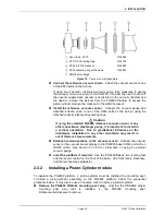
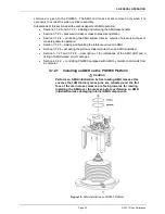
3.5
Piston Position
When operating a PG9000 piston gauge, reference pressure values are defined by loading known mass
values on the piston and adjusting the pressure to float the piston. Piston position is measured and
displayed real time on the MAIN run screen (see Section 3.8) and in the first SYSTEM run screen (see
Section 3.10.5.1). Piston position is used as a criterion for the
Ready/Not Ready
indication as valid
measurements can only be made when the piston is in the correct position (see Section 3.4.1).
The position sensing technology is prone to drift over time and therefore it is important to periodically
adjust the min/max limits of the piston position sensor. When using an AMH, this maintenance
requirement takes on added importance. Please see section 5.2.2 for details on this maintenance
requirement.
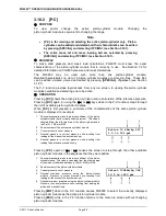
The full piston stroke is
±
4.5 mm from the midstroke position. The stroke is divided into different
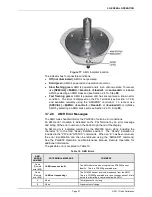
positions and zones as illustrated in Figure 14. These zones are:
•
High and low stops:
The piston is at the minimum or maximum end of travel stroke. These are
mechanical stops that part of the piston-cylinder module. The pressure applied to the piston is higher
(at high stop) or lower (at low stop) than that corresponding to the mass loaded on the piston. The
high and low stop positions are fixed.
•
High and low spring zones:
The combination of pressure and the force of the high or low stop
springs have caused the piston to move away from the mechanical stop. The pressure applied to the
piston is within the equivalent of 2 kg of the pressure corresponding to the mass loaded on the piston.
The high and low spring zones indicate the piston is
about to float
. The spring zone positions are
fixed.
•
High and low measurement zones:
The piston is within the zone in which a
Ready
condition is
valid and a measurement can be made (see Section 3.4.1). The pressure applied to the piston is the
same as the calculated pressure as defined by solving the fundamental pressure equation. The
default value of the high and low measurement zones is ± 2.5 mm centered around the midstroke
position. This value can be adjusted in the SETUP file (see Section 3.11).
•
Midstroke:
The piston is at the middle of the float zone. The reference level as marked on the
PG9000 mounting post corresponds to the bottom of the piston when it’s at the midstroke position.
Содержание PG9000 Series
Страница 10: ...PG9602 OPERATION AND MAINTENANCE MANUAL 2011 Fluke Calibration Page X Notes...
Страница 128: ...PG9602 OPERATION AND MAINTENANCE MANUAL 2011 Fluke Calibration Page 118 Notes...
Страница 164: ...PG9602 OPERATION AND MAINTENANCE MANUAL 2011 Fluke Calibration Page 154 Notes...
Страница 188: ...PG9602 OPERATION AND MAINTENANCE MANUAL 2011 Fluke Calibration Page 178 Notes...
Страница 192: ...PG9602 OPERATION AND MAINTENANCE MANUAL 2011 Fluke Calibration Page 182 Notes...


