LS-1310/1550Laser Source
8
C13+
Z2
R20
Z5
R12
R31
R2
BT1+
BT1-
TP2
TP1
R29
R39
R40
nu02f.eps
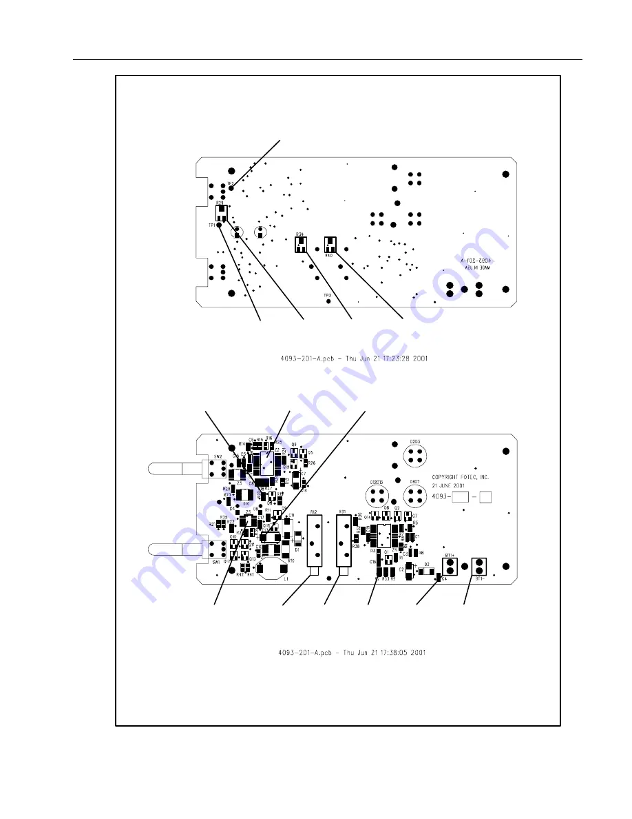
Figure 2. Calibration Measurement and Adjustment Points for SN
≥
79130000
Страница 1: ...r radiation and to prevent eye damage Never look directly into the source connector Though the laser radiation is invisible it can damage your eyes Do not modify the source Do not magnify or otherwise modify the laser output Use only approved connectors and adapters Do not use controls adjustments or procedures not documented or approved by Fluke Corporation Caution While servicing the laser sourc...
Страница 2: ...ance tests and calibration adjustments Fiber optic power meter calibrated at 1310 nm and 1550 nm 0 10 V dc adjustable power supply with a minimum output of 500 mA and a current limit adjustment Fluke 187 DMM digital multimeter equivalent or better 20 MHz digital or analog oscilloscope equivalent or better Optical power meter OPM traceable to local national standards ST ST singlemode fiber patch ca...
Страница 3: ...ad to BT1 on the source connect the negative lead to BT2 1 8 Set the laser source s CW MOD switch to the CW position 1 9 Set the laser source s power switch to either the 1310 nm or 1550 nm position Verify that the laser source LOW BATTERY LED is off and the SOURCE ACTIVE LED is on Step 2 Checking the Laser Drive Voltage Use the following procedure to check the drive voltage for the laser diodes a...
Страница 4: ...LS 1310 1550 Laser Source 4 J2 J4 R14 R4 BT1 BT2 R35 R24 U3 R24 U3 R35 SW1 SW2 R14 R4 J4 J2 Front Back nu01f eps Figure 1 Jumpers and Calibration Measurement and Adjustment Points for SN 79130000 ...
Страница 5: ... 15 mA at 9 2 dBm If the current reaches 60 mA before the power reading reaches 9 2 dBm the laser source requires repair 3 6 Turn off the laser source Disconnect the current meter Reinstall the jumper between J4 1 and J4 2 3 7 With the laser source set to 1310 nm verify that the power reading is 9 2 dBm 0 1 dB 3 8 Adjust the 1310 nm external potentiometer R24 counterclockwise to verify that the la...
Страница 6: ...ce CW MOD switch to the MOD position 4 12 Verify that the power reading is 10 dBm 0 5 dBm Verify that the signal frequency is 2 kHz 100 Hz with a duty cycle of 50 5 4 13 Set the laser source CW MOD switch to CW Turn off the laser source Step 5 Reassembly and Final Test 5 1 Remove the singlemode cable from the laser source Put the dust cap onto the laser source optical ST connector 5 2 Apply insula...
Страница 7: ... 2 V Step 3 Calibrating and Adjusting the 1310 nm Circuit Use the following procedure to make calibration adjustments to the 1310 nm laser diode circuit 3 1 Adjust the dc power supply to 9 V 0 25 V with the output current limited to 250 mA Connect the power supply s positive lead to BT1 connect the negative lead to BT1 3 2 Set up the DMM to measure dc volts less than 2 V Connect the negative probe...
Страница 8: ...LS 1310 1550 Laser Source 8 C13 Z2 R20 Z5 R12 R31 R2 BT1 BT1 TP2 TP1 R29 R39 R40 nu02f eps Figure 2 Calibration Measurement and Adjustment Points for SN 79130000 ...
Страница 9: ...st R40 clockwise until either the power reading is 9 2 dBm 0 1 dB or the current reaches 60 mA A typical current value is 15 mA at 9 2 dBm If the current reaches 60 mA before the power reading reaches 9 2 dBm the laser source requires repair 4 6 With the laser source set to 1550 nm verify that the power reading is 9 2 dBm 0 1 dB 4 7 Adjust the 1550 nm external potentiometer R31 counterclockwise to...
Страница 10: ...Top case 625837 Bottom case 625829 Fiber optic cable assembly ST ST singlemode 662368 Fiber optic adapter ST ST singlemode 625928 9 V battery 614487 LS 1310 1550 Laser Source Instruction Sheet 687290 Table 3 Accessories Description Fluke Model Number Fiber optic cable assembly ST ST singlemode NF100SM Fiber optic cable assembly ST SC singlemode NF110SM Fiber optic cable assembly ST FC singlemode N...