Installation
24
ScanIR3
5.3.3
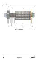
Scanner Head Cable
The scanner head cable comes pre-wired to the processor box by factory default.
Terminal
X4
X3
Pin
1
2
3 6 S 1 2 3 4 5 6 7 8 9 10 11 12 13 14 15 16
Color
gr
een
br
ow
n
yel
low
wh
ite
yel
low
blac
k_1
blac
k_2
yel
low
/ w
hit
e
yel
low
/ br
ow
n
gr
een /
wh
ite
gr
een /
br
ow
n
pink
/ g
rey
blu
e /
red
gre
y / w
hite
gre
y / b
ro
wn
blue
viol
et
re
d
pink
blac
k
gr
ey
Description
Et
he
rne
t
gr
ou
nd
24 V
DC
for
ser
vic
e o
nly
for
ser
vic
e o
nly
for
ser
vic
e o
nly
for
ser
vic
e o
nly
for
ser
vic
e o
nly
for
ser
vic
e o
nly
for
ser
vic
e
on
ly
for
ser
vic
e o
nly
int
er
nal
rel
ay
int
er
nal
rel
ay
trigger
in
put
+
trigger
in
put
-
m
V i
nput
+
m
V i
nput
-
Figure 10: Wiring the Scanner Head Cable
By standard, the cable gland is mounted to the scanner head cable. In case of specific installation
needs, see the mounting structure for the cable gland below for detaching/attaching it.
Figure 11: Cable Gland Composition
1
© Pflitsch GmbH & Co. KG
Scanner Head Cable
Pressure Screw
Sealing Insert
Double Nipple
O-Ring
Connection Thread
Processor Box
Conus Braid

