Maintenance
Troubleshooting
3
3-13
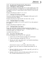
3-15. Supplemental Troubleshooting Procedures
3-16. Checking the Crystal Oscillator
Connect an oscilloscope or counter to pin 54 U1 or to the junction of C12 and
the Y1 crystal. Check for a 32.768-kHz sine wave approximately 600 mV p-p
in amplitude. Note that U2 and the display will not work if the clock circuit is
not working.
Probable related failures include: U1, Y1, or C12.
3-17. Checking The Reference Voltage
Check for a reference voltage of 1.00V dc (adjustable by R8) at pin 14 of U1
or at the junction of R15 and R16.
Probable related failures include: R8, R14, R15, R16, VR1, or CR2.
3-18. Checking Display Drive Voltage
Check that VM (V middle) is 1.6V dc
±
.1V at pin 28 U2 or at the junction of
R11 and R12.
Probable related failures include: R11 or R12.
3-19. Checking Beeper Drive Signal
Put the unit in the Diode Test Mode and short the input leads. Using an
oscilloscope, measure the signal at pin 3 of U1. The signal should be a 4V p-p
symmetrical square wave at about 4.1 kHz.
A probable related failure is: U1
3-20. Tracing the VDC Signal Path
Use the following procedure to trace the VDC signal path:
1.
Set the UUT to the VDC function and apply 2V dc to the input.
2.
Using a DVM, measure the input at J1 for 2V dc.
3.
Measure pin 1 of Z1 input divider for 2V dc. Probable related failures
include: R1, S1, RV1, or RV2.
Note
Measurements in steps 4,5, and 6 may be affected by loading.
4.
Measure Z1 pin 3 for 200 mV dc. Probable related failures are: Z1,
U1.
5.
Measure for 200 mV dc at the active filter input (AFI, pin 26 of U1 or
R9). A probable failures is: U1
6.
Measure for 200 mV at the active filter output (AFO, pin 27 of U1 or
R9). Probable related failures are: R9, C5, or C6.
Содержание 77 Series III
Страница 5: ...77 Series III Service Manual iv...
Страница 7: ...77 Series III Service Manual vi...
Страница 11: ...77 Series III Service Manual 1 2...
Страница 17: ...77 Series III Service Manual 1 8...
Страница 19: ...77 Series III Service Manual 2 2...
Страница 25: ...77 Series III Service Manual 2 8...
Страница 27: ...77 Series III Service Manual 3 2...
Страница 39: ...77 Series III Service Manual 3 14...
Страница 43: ...77 Series III Service Manual 4 2...
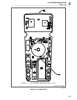
Страница 50: ...List of Replaceable Parts Parts Lists 4 4 9 FLUKE 77 3 4001 aaa06f eps Figure 4 2 A1 Main PCA...
Страница 51: ...77 Series III Service Manual 4 10 FLUKE 77 3 4001 aaa07f eps Figure 4 2 A1 Main PCA cont...
Страница 52: ...5 1 Chapter 5 Schematic Diagrams...
Страница 53: ...77 Series III Service Manual 5 2...
Страница 55: ...77 Series III Service Manual 5 4 FLUKE 77 3 4001 aaa06f eps Figure 5 1 A1 Main PCA...
Страница 56: ...Schematic Diagrams 5 5 5 FLUKE 77 3 4001 aaa07f eps Figure A1 Main PCA cont...

