7037/7038/7040/7041
User's Guide
20
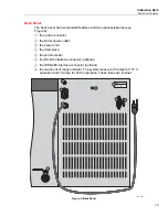
1. The probe connector in the back panel is used for the temperature
controller probe.
2. The stirrer power is provided for the stirring motor.
3. The power cord
4. A drain valve is provided for ease of removing the fluid media from the
bath. Always use a container of adequate size to hold the FULL LOAD of
fluid. Some oils are more easily drained at higher temperatures. (See
caution note in next section.)
5. The serial number is located on the upper right corner of the back panel.
The series is also stamped on this panel. When consulting with an
Authorized Service Center, use the model number and the serial number.
6. If the bath is supplied with a serial RS-232 interface, the interface cable is
attached to the back of the bath at the connector labeled “Serial Port”.
7. If the bath is supplied with a GPIB IEEE-488 interface, the interface cable
is attached to the back of the bath at the connector labeled “IEEE”.
8. The mains out of range indicator is on (red) when the line voltage is low.
See the Warnings in the
Safety Information
section for details.
Bath Tank and Lid
There are two different types of lids. They both have the same overall
dimensions but the optional lid (see Figure 5) has a recirculation pump and the
standard lid has a stirring motor with rectangular access hole. Their features are
described with reference to figure numbers as follows:
1. The top half of the latch attaches the lid to the bath. There are two latches
one on the front and one on the back.
2. The thermometer/liquid level is a hole in the lid for filling and removing of
liquid, checking liquid level and for mounting a thermometer. A hole may be
drilled in the rubber stopper supplied for inserting a thermometer into the
bath.
3. The rectangular access hole (standard lid) may be used to insert the users
device to be thermostatted. To obtain specified control levels this hole must
be covered to prevent thermal disturbance to the bath. Covers may be
purchased separately from Fluke Calibration.
4. The circulation inlet outlet (pump lid) is the access area or the inlet and outlet
for the circulation pump.
5. The stirrer/pump motor drives the stirring propeller to provide mixing of the
bath fluid. Proper mixing of the fluid is important for good constant
temperature stability. The stir motor power cord plugs into the back of the
bath at the power socket labeled “STIRRER”.
6. The probe hole is for the temperature controller probe. The probe must be in
this hole for the bath to operate.
7. A drain valve is provided for ease of removing the fluid media from the bath.
Always use a container of adequate size to hold the full load of fluid. Some
oils are more easily drained at higher temperatures. (See caution note
below.)


