background image

Thermometer

Disassembly and Reassembly

13

zb01f.eps

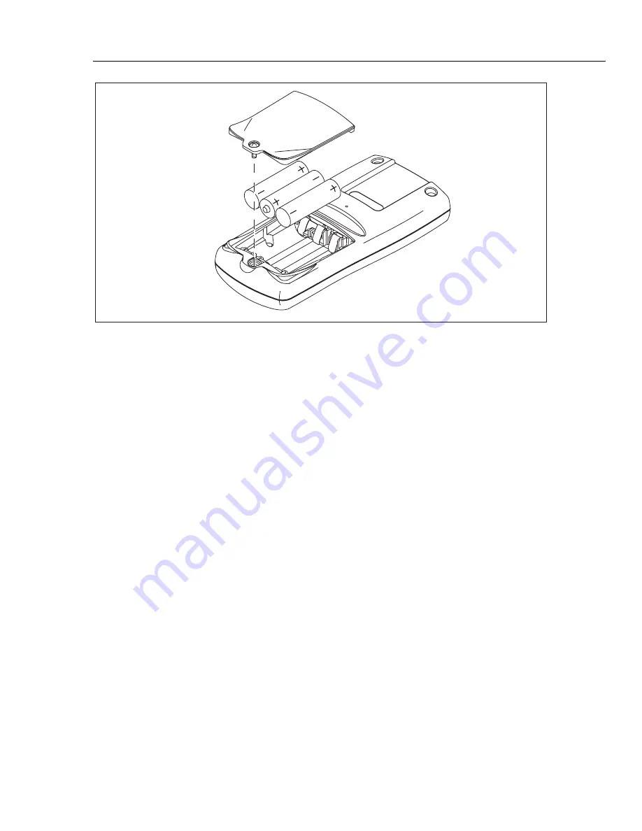
Figure 5. Battery Access

Disassembly and Reassembly

Disassembly and reassembly of the thermometer may be necessary to replace interior
parts. Refer to Figure 6 when disassembling and reassembling the thermometer.

Disassembly

To disassemble the thermometer, follow these steps:

1.


Remove the batteries (see “Changing the Batteries” section).

2.


Remove the two screws located inside the battery compartment.

Caution

  Before proceeding, make sure that you are grounded to

prevent static discharge, which could damage the
thermometer.

  Inside the unit there are parts that can become

contaminated by oils from the skin. These parts should not
be directly handled. When lifting out the elastomeric
connectors and the main switch pad, it is recommended that
tweezers or sterile gloves be used.

3.


Remove the two case bottom screws, located at the LCD-end of the unit and separate
the bottom case from the top case.

4.


Removing any of the interior components of the unit requires removing the Main
PCA. To remove the Main PCA, place the top case face down and remove the two
screws that attach the Main PCA to the top case. Gently lift the Main PCA out of the
top case. The IR Lens, small Isothermal PCA, backlight, elastomeric connectors, and
the LCD may all lift out attached to the Main PCA.

5.


If the Isothermal PCA separates from the Main PCA, the Isothermal PCA, IR Lens,
backlight, elastomeric connectors, and the LCD will still be in the top case. Lift them
out of the top case after the Main PCA is removed.

Содержание 51

Страница 1: ... 51 52 53 54 Series II Thermometer Service Manual PN 1276123 October 1999 1999 Fluke Corporation All rights reserved Printed in USA All product names are trademarks of their respective companies ...

Страница 2: ... the warranty period To obtain warranty service contact your nearest Fluke authorized service center or send the product with a description of the difficulty postage and insurance prepaid FOB Destination to the nearest Fluke authorized service center Fluke assumes no risk for damage in transit Following warranty repair the product will be returned to Buyer transportation prepaid FOB Destination If...

Страница 3: ...t Procedure 6 Ice Bath Construction 6 Ice Bath Test 7 Verification of IR Communications Port Fluke 53 and 54 8 Calibration and Offset Adjustment 9 A D Calibration 9 Reference Junction Calibration 11 Using the Offset to Adjust for Variation Between Thermocouples 11 Basic Maintenance 12 Cleaning the Thermometer 12 Changing the Batteries 12 Disassembly and Reassembly 13 Disassembly 13 Reassembly 14 R...

Страница 4: ...51 52 53 54 Series II Service Manual ii ...

Страница 5: ...iii List of Tables Table Title Page 1 International Electrical Symbols Used in this Manual 2 2 Recommended Test Equipment 5 3 Performance Test Values K Type Thermocouple 8 4 Replaceable Parts 15 ...

Страница 6: ...51 52 53 54 Series II Service Manual iv ...

Страница 7: ...t of Figures Figure Title Page 1 Display Segments 6 2 Ice Bath Test Equipment Connections 7 3 Calibration Connections 9 4 Calibration Button Access 10 5 Battery Access 13 6 Exploded View Model 54 is Shown 17 ...

Страница 8: ...51 52 53 54 Series II Service Manual vi ...

Страница 9: ...arts that can be damaged by static discharge Follow the standard practices for handling static sensitive devices Introduction This manual provides the following service information for the 51 52 53 and 54 Series II Thermometers hereafter referred to as the thermometer Precautions and safety information Specifications Performance tests Calibration and adjustment Basic maintenance Replaceable parts ...

Страница 10: ...in this manual Table 1 International Electrical Symbols Used in this Manual B Low Battery Important information Complies with relevant Canadian Standards Association directives Complies with European Union directives Precautions and Safety Information Use the thermometer only in the ways specified in the 51 52 Series II Users Manual and the 53 54 Series II Users Manual If the thermometer is used i...

Страница 11: ...por or dust Do not apply more than the rated voltage as marked on the thermometer between the thermocouple s or between any thermocouple and earth ground Models 52 and 54 Measurement errors may occur if voltages on the measurement surfaces result in potentials greater than 1 V between the two thermocouples When potential differences are anticipated between the thermocouples use electrically insula...

Страница 12: ...C 328 o F to 2501 o F T type 250 o C to 400 o C 418 o F to 752 o F E type 150 o C to 1000 o C 238 o F to 1832 o F N type 200 o C to 1300 o C 328 o F to 2372 o F R and S type 0 o C to 1767 o C 32 o F to 3212 o F Display Resolution 0 1 o C o F K 1000 o 1 0 o C o F K 1000 o Measurement Accuracy J K T E and N type 0 05 of reading 0 3 o C 0 5 o F below 100 o C 148 o F add 0 15 of reading for J K E and ...

Страница 13: ...Thermos Mercury Thermometer either C or F 0 02 C Resolution 0 05 F Resolution Princo Model ASTM56C Princo Model ASTM56F DB9 Adapter Connector Fluke P N 804549 IR Adapter Fluke P N 690518 PC with Microsoft Windows installed Performance Tests Performance tests are recommended for incoming inspection periodic maintenance and for checking the thermometer s specifications If the thermometer fails any p...

Страница 14: ... to a Fluke service center Ice Bath Construction To begin the performance test first construct an ice bath as follows 1 Prepare a Dewar Flask by drilling two holes in its cap to accept the Mercury thermometer and thermocouple wires or use a standard laboratory cork 2 Fill the Dewar Flask with shaved or crushed ice made from distilled water 3 Fill the Dewar Flask with enough distilled water so that...

Страница 15: ... Figure 2 Allow the setup to thermally stabilize at least 5 minutes after inserting the thermocouple into the thermometer 3 Verify that the ice bath temperature reads 0 0 o C 0 06 o C on the Mercury thermometer 4 Short or apply 0 mV to the copper wires at the Calibrator 5 Verify the thermometer reads 0 0 o C 0 3 o C 6 If this test fails reposition the thermocouple wires and Mercury thermometer to ...

Страница 16: ...Programs Accessories HyperTerminal 4 Open up a New Connection with a name like Fluke 54 IR Test 5 When the Connect To box appears select the COM1 or COM2 the port that the IR adapter cable is plugged into 6 Select Port Settings 9600 baud rate 8 data bits no parity 1 stop bit and no flow control 7 Under File select properties Verify that the correct port is selected Click on Configure Verify that p...

Страница 17: ...of the thermometer follow these steps 1 Connect the calibrator to the T1 input of the thermometer using copper non thermocouple wire and a copper thermocouple connector Refer to Figure 3 for proper equipment connections 2 Turn the thermometer on with a small blunt probe press the calibration button located on the back and in the center of the thermometer Refer to Figure 4 5700A Calibrator 51 52 53...

Страница 18: ... allow the output to stabilize Note For steps 6 and 8 keep hand and body motion to a minimum while the thermometer takes A D readings 6 Press E Wait while it takes A D readings 7 When the thermometer prompts for 8 set the Calibrator to 8 0000 mV Allow the output to stabilize 8 Press E on the thermometer and wait while it takes A D readings The thermometer now shows the measured value in the bottom...

Страница 19: ... type using the D K N and Ebuttons 4 Enter calibration mode refer to the A D Calibration section step 2 5 Using K or N select CAL rEF and press E 6 Press K or N until the upper display matches the known temperature Note Once adjusted do not change units C F or K until the thermometer is in measurement mode 7 Press the E button 8 CAL donE appears then press E to store the calibration in memory 9 To...

Страница 20: ...ing Replace the batteries as soon as the low battery indicator B appears The possibility of false readings increases when the batteries are low False readings can lead to personal injury To avoid electrical shock disconnect the thermocouple s before opening the battery door Caution Do not attempt to recharge the batteries Do not dispose of the batteries by placing them in fire Follow local laws or...

Страница 21: ...ts should not be directly handled When lifting out the elastomeric connectors and the main switch pad it is recommended that tweezers or sterile gloves be used 3 Remove the two case bottom screws located at the LCD end of the unit and separate the bottom case from the top case 4 Removing any of the interior components of the unit requires removing the Main PCA To remove the Main PCA place the top ...

Страница 22: ...klight with the guide that is molded into the top case The left corner of the backlight should fit directly over this guide and the bottom right side of the backlight should also be lined up with but not over a similar guide on the right side of the open top case 4 Install the two LCD elastomeric connectors Rebuilding the Main PCA When reinstalling the Main PCA make sure that the Isothermal PCA an...

Страница 23: ...y screw the bottom case to the top case reinstall the batteries and screw the battery compartment shut Replaceable Parts Refer to Table 4 for all replacement part numbers and Figure 6 for part locations Unless specified in the Model Number column all parts are for all units To order replaceable parts see the Service Centers section of this manual Table 4 Replaceable Parts Item Number Qty Fluke Par...

Страница 24: ...AL LCD DECAL 51 52 53 54 12 1 674747 BACKLIGHT All 13 1 1272438 HOLSTER FLEX STAND ASSEMBLY All 14 2 643830 SCREW PH P METRIC PT STL K35 14MM All 15 1 669793 669788 669785 669777 KEYPAD KEYPAD KEYPAD KEYPAD 51 52 53 54 16 1 804705 CONNECTOR ELASTOMERIC SWITCH TO PWB 1 200 L All 17 1 800836 LCD MULTIPLEXED All Not shown 1 1276106 CD ROM CD ROM FLUKE 50 SERIES II CD ROM contains 51 52 Series II User...

Страница 25: ...Thermometer Replaceable Parts 17 13 4 3 1 8A 2 8D 8F 14 8C 8B 15 17 11 9A 9B 6 10 5 16 7 12 8E zb07f eps Figure 6 Exploded View Model 54 is Shown ...

Страница 26: ...51 52 53 54 Series II Service Manual 18 ...

Страница 27: ...disassembly 13 display segments 6 E electrical symbols 2 H HyperTerminal 8 I ice bath construction 6 equipment connections 7 test 7 L LCD reinstalling 14 M Main PCA rebuilding 14 reinstalling 15 maintenance basic 12 batteries changing 12 cleaning 12 P parts diagram 17 list of replaceable 15 performance tests 5 display test 5 IR communications port verification 8 keypad test 6 test values k type th...

Страница 28: ...autions and warnings 3 service centers phone numbers world wide web address 2 specifications electrical 4 environmental 4 general 4 T test equipment performance testing and calibration 5 U Users Manual 51 52 Series II 1 53 54 Series II 1 W warnings 1 12 ...

Отзывы: