2680A/2686A
Users Manual
4-24
12
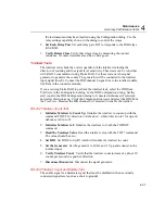
11
13 14 15 16 17 18 19 20
2
1
3
4
5
6
7
8
9
10
SOURCE
(4-WIRE)
SENSE
(4-WIRE)
H L H L H
L H
L H
L H
L H
L H
L H
L H
L
H L H
L H
L H
L H
L H
L H
L H
L H
L
INPUT
MODULE
HI
HI
LO
LO
HI
OUTPUT
V A
SENSE
V
AUX
CURRENT
GUARD GROUND
WIDEBAND
Ω
Ω
5700A
H L
alg68f.eps
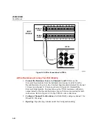
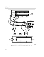
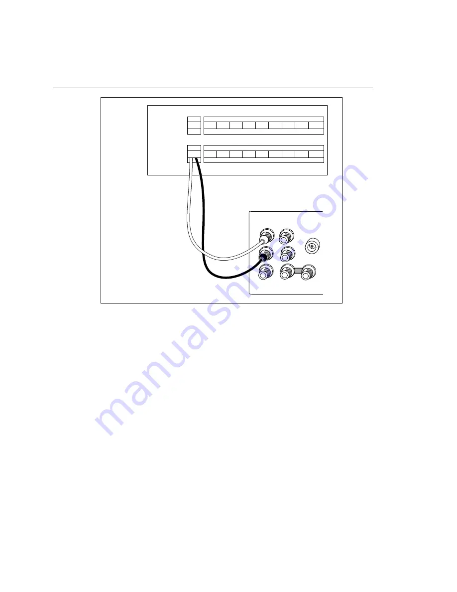
Figure 4-3. 2-Wire Connections to 5700A
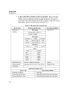
4-Wire Resistance Accuracy Test (PAI Module)
1.
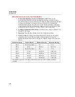
Connect the Resistance Source to Channels 1 and 11
Remove the
Universal Input module from the instrument and connect a cable from the
Decade Resistance Source to the Universal Input module terminals for channel
1 (Sense) and channel 11 (Source) as shown in Figure 4-4. Reinstall the
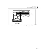
Universal Input module. You may also use the 5700A resistance calibration
output instead of the Decade Resistance Source. Tables are provided for both
connections. Refer to Figure 4-5 for the 5700A 4-wire connections.
2.
Configure Channel 1 for Resistance
In Fluke DAQ, configure channel 1 for
Ohms 4W, 300 range.
3.
Open Spy
Open the Spy window under the Configuration dialog.
Содержание 2680A
Страница 8: ......
Страница 14: ...2680A 2686A Users Manual vi ...
Страница 20: ...2680A 2686A Users Manual 1 2 ...
Страница 98: ...2680A 2686A Users Manual 2 62 ...
Страница 196: ......
Страница 228: ...2680A 2686A Users Manual A 32 ...
Страница 236: ...2680A 2686A Users Manual C 4 ...
Страница 242: ...2680A 2686A Users Manual D 6 ...
Страница 274: ...2680A 2686A Users Manual 6 ...

