1744/1743
Users Manual
24
1.
Connect the voltage test leads to the outputs of the voltage
transformers (VTs).
2.
In PQ Log, select the measuring range with P-N logging and
matching nominal voltage.
3.
Enter the correct converter/transformer ratio for current and voltage.
Note
Current clamp sets are available for 1 A current transformers.
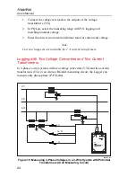
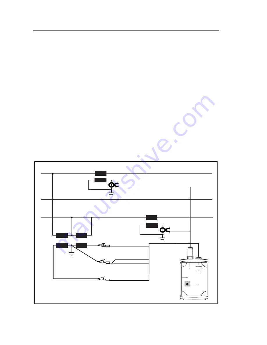
Logging with Two Voltage Converters and Two Current
Transformers
In 3-phase 3-wire systems with two voltage converters (VTs) and two current
transformers (CTs) in an Aron or Blondel measuring circuit, the Logger can
measure only phase-phase (P-P, Delta).
L1
L2, N
L1
L3
L2
L3
POWER LOGGER
1743
START
STOP
POWER
2
3
2
S
R
I
N
I
3
I
2
I
1
V
3
V
2
V
1
CURRENT INPUT
10 VRMS MAX
L1/A
L2/B
L3/C
N
5 VA
45 -65 Hz
MEASUREMENT INPUT
SUPPLY INPUT
830 VRMS MAX CAT
600 V CAT
300 V CAT
100 -350 V
660 V MAX
88 -660 V
egb009.eps
Figure 10. Measuring 3-Phase Voltages in a 3-Wire System with Potential
Transformers (Aron Measuring Circuit)
Содержание 1743
Страница 11: ...Contents continued iii Timeplot diagram 60 UNIPEDE DISDIP Table 61 Cumulative Frequency Harmonics 62 Index ...
Страница 12: ...1744 1743 Users Manual iv ...
Страница 14: ...1744 1743 Users Manual vi ...
Страница 16: ...1744 1743 Users Manual viii ...
Страница 80: ...1744 1743 Users Manual 64 Voltage Harmonics 32 Voltage interruptions 31 Voltage variations 28 ...

