background image


HDX USER INSTRUCTIONS  ENGLISH  85392696 - 01/11 

Page 55 of 60 

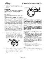
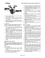
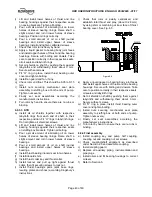
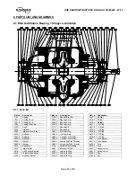
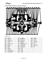
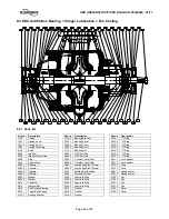
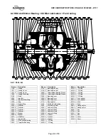
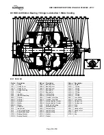
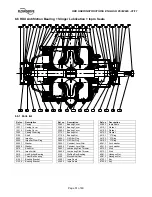
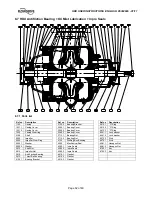
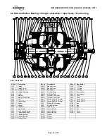
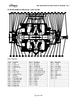
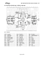
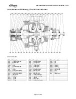
8.10 HDX Antifriction B Coke Crusher 


8.10.1  Parts list  


Ref no 

Description 


Ref no


Description


 Ref 

no


Description


1100  Casing 

 3712.1 

Bearing 

Nut 

 4610.2 

“O” 

Ring 

1221.1 

Casing Cover 


3712.2 

Bearing Nut 


4610.3 

“O” Ring 

1221.2 

Casing Cover 


3854.1 

Oil Filter Plug 


6541.1 

Lock washer 

1500 

Casing Wear ring 


3854.2 

Oil Filter Plug 


6541.2 

Lock washer 

2100  Shaft 

 3855.1 

Constant 

Level 

Oiler 

 6550.1 

Cooling 

Line 

2200  Impeller 

 3855.2 

Constant 

Level 

Oiler 

 6550.2 

Cooling 

Line 

2215.1 Coke 

Crusher 

  3862.1 Lubricating 

Disk 

Thrower 

  6572.2 Stud 

2215.2 Coke 

Crusher 

  3862.2 Lubricating 

Disk 

Thrower 

  6572.1 Stud 

2300 

Impeller Wear Ring 


4132 

Stuffing Box Bushing 


6581.1 

Hexagon Nut 

2910 

Shaft Nut 


4200 

Mechanical Seal 


6581.2 

Hexagon Nut 

2912 

Impeller Nut 


4300.1 

Inpro Seal  


6700.1 

Key 

3010 

Anti-Friction Bearing 


4300.2 

Inpro Seal 


6700.2 

Key 

3013 

Thrust Ball bearing 


4300.3 

Inpro Seal 


3130.1 Bearing 

Bracket 


  4510.1 Gasket 


3130.2 Bearing 

Bracket 

  4510.2 Gasket 


3260.1 Bearing 

Cover 

  4510.3 Gasket 


3260.2 Bearing 

Cover 

  4610.1 “O” 

Ring 


3260.3 

Bearing 

Cover 


Содержание HDX Series

Страница 1: ...le stage double suction radially split volute type centrifugal pumps PCN 85392696 01 11 E Original instructions Installation Operation Maintenance These instructions must be read prior to installing operating using and maintaining this equipment ...

Страница 2: ... 4 6 Piping 20 4 7 Final shaft alignment check 22 4 8 Electrical connections 22 4 9 Protection systems 22 5 COMMISSIONING START UP OPERATION AND SHUTDOWN 23 5 1 Pre commissioning procedure 23 5 2 Pump Lubricants 28 5 3 Direction of rotation 30 5 4 Guarding 31 5 5 Priming and auxiliary supplies 31 5 6 Starting the pump 31 5 7 Operating checks 31 5 8 Normal Start Up 33 5 9 Stopping the pump 33 5 10 ...

Страница 3: ...storage 2 4 1 11 Lubrication 5 1 1 23 Maintenance to avoid the hazard 1 6 4 7 8 Maintenance 6 33 Maintenance schedule 6 2 34 Marking 1 6 4 2 7 Mechanical seals 6 8 3 39 Nameplate and safety labels 1 7 8 Noise level 1 9 9 Ordering of spares 6 3 1 35 Other relevant documentation and manuals 10 59 Parts list and Drawings 8 46 Performance and operating limits 3 4 14 Personnel qualification and trainin...

Страница 4: ...e the Directives and any additional Approvals cover important safety aspects relating to machinery and equipment and the satisfactory provision of technical documents and safety instructions Where applicable this document incorporates information relevant to these Directives and Approvals To confirm the Approvals applying and if the product is CE marked check the serial number plate markings and t...

Страница 5: ...dy possess the necessary knowledge and skill appropriate training and instruction must be provided If required the operator may commission the manufacturer supplier to provide applicable training Always coordinate repair activity with operations and health and safety personnel and follow all plant safety requirements and applicable safety and health laws and regulations 1 6 3 Safety action This is...

Страница 6: ...rea action must be taken to avoid accidental contact If complete protection is not possible the machine access must be limited to maintenance staff only with clear visual warnings and indicators to those entering the immediate area Note bearing housings must not be insulated and drive motors and bearings may be hot If the temperature is greater than 80 C 175 F or below 5 C 20 F in a restricted zon...

Страница 7: ...00 C 572 F 450 C 842 F Consult Flowserve Consult Flowserve 115 C 239 F 180 C 356 F 275 C 527 F 400 C 752 F The responsibility for compliance with the specified maximum liquid temperature is with the plant operator Temperature classification Tx is used when the liquid temperature varies and the pump could be installed in different hazardous atmospheres In this case the user is responsible for ensur...

Страница 8: ...put to the liquid This can occur if the pump is stationary or running Bursting of liquid containing parts due to freezing must be avoided by draining or protecting the pump and ancillary systems Where there is the potential hazard of a loss of a seal barrier fluid or external flush the fluid must be monitored If leakage of liquid to atmosphere can result in a hazard the installation of a liquid de...

Страница 9: ...vel at some speeds Consult a Noise Specialist for the combined calculation For units driven by equipment other than electric motors or units contained within enclosures see the accompanying information sheets and manuals Typical sound pressure level dBA LB pAB at 1 m reference 20 μPa LB wAB sound power 1pW where LB pAB 85 dBA 3500 rpm 2900 rpm 1750 rpm 1450 rpm Motor size and speed kW hp Pump only...

Страница 10: ...ecessary a lifting beam can be placed between the winch and the load When heavy pieces are lifted up never stay or work under the load or in the area which could be in the path of the load if it were to swing or fall away Never leave a load hanging from a winch The acceleration or the slowing down of lifting equipment must stay in the safety limits for the staff A winch must be positioned in such ...

Страница 11: ...foreign materials or water If necessary clean and preserve the interior parts as noted above to restore the parts to the as shipped condition Install or replace covers and fasten securely 2 4 1 2 Storage If at all possible the pump and its component parts should be stored indoors where they will be protected from the elements In no case should any pump element be subjected to extended periods of s...

Страница 12: ...plied by the purchaser Upon completion of the inspection the FLOWSERVE representative shall submit a report to the purchaser and to the Manager of Customer Service stating in detail the results of the inspection One month prior to installation of the equipment a FLOWSERVE representative is to be employed to conduct a final inspection This inspection will be made to assure that the requirements of ...

Страница 13: ...er is mounted with an interference fit and keyed to the shaft positively secured against axial movements by a step in the shaft and a threaded shaft nut Impellers are designed to handle hot liquids close to their boiling points The symmetric pressure distribution acting on impeller shrouds ensures complete axial balance of the rotor 3 3 3 Wearing Rings The casing and the impeller are fitted with r...

Страница 14: ...er rated capacity and rated head for a liquid with a particular viscosity For a given flow rate the total head reduces with increased viscosity and increases with reduced viscosity Also for a given flow rate the power absorbed increases with increased viscosity and reduces with reduced viscosity When contemplating operation at some viscosity other than the one for which the pump was originally des...

Страница 15: ...h the relevant explosion protection regulations See section 1 6 4 Products used in potentially explosive atmospheres 4 1 Location The pump should always be located as near as possible to the suction supply Install the unit close to the source of the liquid to be pumped It is desired to simplify the suction and discharge piping layout When selecting the location be sure to allow adequate space for ...

Страница 16: ...op with a chisel to afford a good hold for grout In case of installation over a steel structure platform ensure that the top of the steel structure is cleaned and degreased In order to obtain the parallelism and flatness of pads required by API standard baseplate has to be properly levelled by levelling screws provided on it and clamping the baseplate at the foundation bolts only For proper detail...

Страница 17: ... is a matter of personal preference whether the levelling wedges under the baseplate should be removed after grouting If you do not want to remove the wedges carefully mark their locations before pouring grout Before grouting level machined pads of baseplate in both directions and perform a rough shaft coupling alignment Alignment after grout has set will not be possible if above is not satisfacto...

Страница 18: ...isalignment The shafts must be aligned within the limits given within this section Adjustment to correct the alignment in one direction may alter the alignment in another direction Always check in all directions after making any adjustment Coupled equipment must be aligned to minimise unnecessary stresses in shafts bearings and coupling Flexible couplings will not compensate for appreciable misali...

Страница 19: ...ve in the shaft to a pointer fixed to the motor body refer to Motor Manufacture s instructions 4 5 2 3 Alignment using a graph Reverse Alignment Ensure pump and driver are isolated electrically and the half couplings are disconnected The alignment MUST be checked Although the pump will have been aligned at the factory it is most likely that this alignment will have been disturbed during transporta...

Страница 20: ... make adjustments Do not attempt any maintenance inspection repair or cleaning in the vicinity of rotating equipment Such action could result in injury to operating personnel Before attempting any inspection or repair on the pump the driver controls must be in the off position locked and tagged to prevent restarting equipment and injury to personnel performing service on the pump 4 5 5 Assemble co...

Страница 21: ...lled as close to the pump as possible The open area of the strainer should have a minimum of a 3 to 1 ratio to the area of the pump inlet Pressure gauges should be installed on both sides of the strainer so the pressure drop across the strainer can be measured when the unit is operated Typical temporary suction strainer Pressure gauges should be installed on both sides of the screen so that the pr...

Страница 22: ...UROPEAN DIRECTIVE on electromagnetic compatibility when wiring up and installing equipment on site Attention must be paid to ensure that the techniques used during wiring installation do not increase electromagnetic emissions or decrease the electromagnetic immunity of the equipment wiring or any connected devices If in any doubt contact Flowserve for advice The motor must be wired up in accordanc...

Страница 23: ...which may have accumulated during installation Take all possible care not to contaminate your system c Install suction strainer if required See Section 4 6 2 1 d Fill the bearing housings with the appropriate oil to the correct level Bearing must receive a small amount of oil prior to starting to ensure adequate lubrication at start up Refer to Section 5 1 1 e Turn pump rotor by hand or with a str...

Страница 24: ...ng the bearing housing reservoir flush out the housing thoroughly with safety solvent and a leading grade of flushing oil compatible with the lubrication oil that will be used The oil level must be maintained at the correct level oil lack may cause overheating and failure of the bearings while exceeding the correct level can result in leakage from the labyrinth seals The constant level oiler can b...

Страница 25: ...earings Figure 5 5 5 1 2 TRICO oiler setting standard TRICO is used only on ball ball lubrication and sleeve ball lubrication a Initial fill via top of housing using overflow plug to establish correct level b Release thumb screw and remove bottle Establish a measurement from the centre line of the oiler connection in bearing housing to the upper cross arm of 6 mm 0 24 in this can be obtained by co...

Страница 26: ...ion from use and contamination from dirt and moisture which is the cause of premature bearing wear For oil lubricated pumps fill the bearing housing with correct grade of oil to the correct level i e constant level oiler bottle standard configuration and sight glass when fitted on request Figure 5 7 Sight glass 5 1 4 Replenishment Replenish the oil in the oiler as required for ball ball and sleeve...

Страница 27: ... bearing housing Ball ball lubrication NPT inlet connection NPT vent connection NPT drain connection Sleeve ball lubrication Line bearing to NPT adapter oil mist inlet connection NPT vent connection NPT drain connection Thrust bearing NPT inlet connection NPT vent connection NPT drain connection Figure 5 9 Remove inlet and outlet pipe plugs from above connections Install appropriate reclassifier i...

Страница 28: ...l HL46 BP Energol HL68 BP BP Energol HLP46 BP Energol HLP68 CASTROL Perfecto T46 Perfecto T68 TURBELF SA46 TURBELF SA68 Elf ELFOLNA DS46 ELFOLNA DS68 TERESSO 46 TERESSO 68 Esso NUTO H46 NUTO H68 LSC LSO 46 LSO 68 LSO 100 for oil mist Synthetic oil Synthetic oil Synthetic oil Mobil DTE oil medium Mobil DTE oil heavy medium Mobil DTE15M Mobil DTE26 Mobil Mobil DTE25 Q8 Verdi 46 Q8 Verdi 68 Q8 Q8 Hay...

Страница 29: ... 3 7 0 056 0 0034 The bearing housing size can be identified from the identifying marks cast on the housing on the horizontal centre line in the opposite side to the oiler and from the thrust bearing side indicated by nameplate Bearing Designation Oil Fill Capacity D E Side N D E Side Bearing Housing Size Radial Bearing Thrust Bearing litres oz litres oz EB 1 6310 2 x 7310 BG 0 75 25 4 1 00 33 8 E...

Страница 30: ...commended Oil Temperature At Start Up 15 6 C 60 F Desirable Operating Temperature 60 71 C 140 160 F Oil Level Above Oil Connection Centre line 6 mm When the starting temperature is below 10 C 14 F for long time it s suggested to use a synthetic oil Other drivers and gearboxes if appropriate should be lubricated in accordance with their manuals In the case of product lubricated bearings the source ...

Страница 31: ...hour e Prime pump and ensure suction valve is open Ensure flushing and or cooling heating liquid supplies if required are turned ON before starting the pump Before starting or while operating the pump the casing and suction line must be completely filled with the liquid being pumped The rotating parts depend on this liquid for lubrication and the pump may seize if operated without liquid f Ensure ...

Страница 32: ...r vibration monitoring at the bearings is recommended If bearing temperatures are to be monitored it is essential that a benchmark temperature is recorded at the commissioning stage and after the bearing temperature has stabilized see 5 2 4 1 for temperature limits When a oil temperature sensor is provided set the alarm at 82 C 180 F and the trip at 90 C 194 F for high ambient temperature and or h...

Страница 33: ... decide how to evaluate the implications of any change If in doubt contact your nearest Flowserve office 6 MAINTENANCE 6 1 General It is the plant operator s responsibility to ensure that all maintenance inspection and assembly work is carried out by authorized and qualified personnel who have adequately familiarized themselves with the subject matter by studying this manual in detail See also sec...

Страница 34: ...w Temperature Flows Vibration Pressures Etc c Check motor current driver power d Check that there are no abnormal fluids or lubricant leaks static and dynamic seals and that any sealant systems if fitted are full and operating normally e Check that shaft seal leaks are within acceptable limits f Check all lubricant levels i e bearing housing oilers seal Plan 52 53 seal supply systems as applicable...

Страница 35: ...air parts after the pump has been put into service undersized stationary rings or oversized impeller rings will not be furnished unless specifically requested by the customer If undersize or oversize rings are desired the amount of undersize or oversize required on the I D or the O D must be stated by the customer in the repair order It is recommended as insurance against delays that spare parts b...

Страница 36: ...sonnel when attempting to drain pump Protective devices of suitable protective materials must be worn when draining pump Before attempting any maintenance work on pumps in vacuum service the pumps must be isolated from suction and discharge system then carefully vented to return pressure in pump casing to atmospheric pressure Remove the pipe plug s from the top of the bearing housing s and check t...

Страница 37: ...ough so that lower half sleeve bearing can be removed g Unbolt and remove lower half of thrust bearing housing h Release locking tab of thrust bearing lock washer Loosen and remove thrust bearing lock nut and lock washer i Remove thrust bearing assembly using a puller that will bring pressure against inner bearing race only j Remove oil rings Unscrew set screws and remove inboard oil shield togeth...

Страница 38: ...ng down and damage the shaft d Remove stuffing box gaskets e The rotating element may now be withdrawn It is essential that this operation is carried out as carefully as possible to avoid damage to the shaft and wear rings f Unscrew the impeller locking nut using a pin spanner wrench Remove the nut g Clean shaft and remove impeller as follows h Apply heat to periphery of impeller until temperature...

Страница 39: ... replaced as necessary b It is recommended that when reassembling mechanical seal new O rings and gaskets be used c Refer to manufacturers drawing for assembly of mechanical seal Refer to mechanical seal section within this manual for further details 6 8 4 Stuffing Box Bushings If fitted a Check the stuffing box bushes and replace if cocked and or worn b To replace chill the new bushings to 20 C a...

Страница 40: ...ss extreme care is used when removing an anti friction bearing the bearing may be damaged to the extent that is no longer useable Always check the bearing immediately after removal for any imperfections or any play between the races It is recommended that new bearings be used for replacement of removed bearings since very often damage caused by removal cannot be detected until the pump is put into...

Страница 41: ...aution if ring is removed by grinding so as not to damage impeller hubs IMPELLER HAND GRINDER IMPELLER RING Figure 6 3 b Make sure ring fits on impeller are free of nicks or burrs Heat new ring to 107 C 225 F and install on impeller Drill and tap new holes in impeller spaced half the circular distance from the previously used holes in the impeller See sketch below Figure 6 4 Impeller wear rings wh...

Страница 42: ...over thrust and line bearings g Locate bearing housings to their respective location on stuffing box brackets and tighten bolting h Fix both inner bearing covers to bearing housings i Position outer bearing covers and tighten bolting Ensure that new gaskets are fitted j Set labyrinth ring on line bearing cover and secure oil shield with set screws k Install nuts securing mechanical seal plate asse...

Страница 43: ...box brackets Tighten all bolting c Pour a small amount of lubricating oil on lower halves of sleeve bearing linings Raise shaft a slight amount and roll in lower halves of sleeve bearings d Pour a small amount of oil on shaft journal bearings and install upper halves of sleeve bearings e Install thrust bearing inboard seal in two halves f Install inboard shim g Install thrust collar key and thrust...

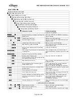
Страница 44: ...rough mechanical seal sleeve joints casing joint or pipe plugs Check and replace faulty parts CONSULT FLOWSERVE z z Foot valve too small Investigate replacing the foot valve z z Foot valve partially clogged Clean foot valve z z z z Inlet of suction pipe insufficiently submerged Check out system design z z z Speed too low CONSULT FLOWSERVE z Speed too high CONSULT FLOWSERVE z z z Total head of syst...

Страница 45: ...r out of balance resulting in vibration z z z Abrasive solids in liquid pumped z z Internal misalignment of parts preventing seal ring and seat from mating properly Check and CONSULT FLOWSERVE z z Mechanical seal was run dry Check mechanical seal condition and source of dry running and repair z z Internal misalignment due to improper repairs causing impeller to rub Check method of assembly possibl...

Страница 46: ...712 2 Bearing Nut 4610 3 O Ring 2300 Impeller Wear Ring 3854 1 Oil Filter Plug 4610 4 O Ring 2540 1 Deflector 3854 2 Oil Filter Plug 4610 5 O Ring 2540 2 Deflector 3855 1 Constant Level Oiler 4610 6 O Ring 2540 3 Deflector 3855 2 Constant Level Oiler 6541 1 Lock washer 2905 1 Washer 3862 1 Lubricating Disk Thrower 6541 2 Lock washer 2905 2 Washer 3862 2 Lubricating Disk Thrower 6572 2 Stud 2910 Sh...

Страница 47: ...1 1 Lock washer 2100 Shaft 3712 1 Bearing Nut 6541 2 Lock washer 2200 Impeller 3712 2 Bearing Nut 6572 2 Stud 2300 Impeller Wear Ring 4132 Stuffing Box Bushing 6572 1 Stud 2540 1 Deflector 4200 Mechanical Seal 6581 1 Hexagon Nut 2540 2 Deflector 4330 1 Labyrinth Ring 6581 2 Hexagon Nut 2540 3 Deflector 4330 2 Labyrinth Ring 6700 1 Key 2905 1 Washer 4330 3 Labyrinth Ring 6700 2 Key 2905 2 Washer 45...

Страница 48: ...54 2 Oil Filter Plug 4610 7 O Ring 2500 Ring 3855 1 Constant Level Oiler 6541 1 Lock washer 2510 Spacer Ring 3855 2 Constant Level Oiler 6541 2 Lock washer 2540 1 Deflector 3862 1 Lubricating Disk Thrower 6572 2 Stud 2540 2 Deflector 3862 2 Lubricating Disk Thrower 6572 1 Stud 2540 3 Deflector 4132 Stuffing Box Bushing 6581 1 Hexagon Nut 2540 4 Deflector 4200 Mechanical Seal 6581 2 Hexagon Nut 290...

Страница 49: ...ing 2200 Impeller 3260 2 Bearing Cover 6541 1 Lock washer 2300 Impeller Wear Ring 3260 3 Bearing Cover 6541 2 Lock washer 2500 Ring 3712 1 Bearing Nut 6572 2 Stud 2510 Spacer Ring 4132 Stuffing Box Bushing 6572 1 Stud 2540 1 Deflector 4200 Mechanical Seal 6581 1 Hexagon Nut 2540 2 Deflector 4330 1 Labyrinth Ring 6581 2 Hexagon Nut 2540 3 Deflector 4330 2 Labyrinth Ring 6700 1 Key 2540 4 Deflector ...

Страница 50: ... Ring 2300 Impeller Wear Ring 3854 2 Oil Filter Plug 4610 6 O Ring 2540 1 Deflector 3855 1 Constant Level Oiler 6541 1 Lock washer 2540 2 Deflector 3855 2 Constant Level Oiler 6541 2 Lock washer 2540 3 Deflector 3862 1 Lubricating Disk Thrower 6550 1 Cooling Line 2905 1 Washer 3862 2 Lubricating Disk Thrower 6550 2 Cooling Line 2905 2 Washer 4132 Stuffing Box Bushing 6572 2 Stud 2910 Shaft Nut 420...

Страница 51: ...2 2 Bearing Nut 4610 1 O Ring 2200 Impeller 3854 1 Oil Filter Plug 4610 2 O Ring 2300 Impeller Wear Ring 3854 2 Oil Filter Plug 4610 3 O Ring 2905 1 Washer 3855 1 Constant Level Oiler 6541 1 Lock washer 2905 2 Washer 3855 2 Constant Level Oiler 6541 2 Lock washer 2910 Shaft Nut 3862 1 Lubricating Disk Thrower 6572 2 Stud 2912 Impeller Nut 3862 2 Lubricating Disk Thrower 6572 1 Stud 3010 Anti Frict...

Страница 52: ...0 3 O Ring 1500 Casing Wear ring 3260 3 Bearing Cover 6541 1 Lock washer 2100 Shaft 3712 1 Bearing Nut 6541 2 Lock washer 2200 Impeller 3712 2 Bearing Nut 6572 2 Stud 2300 Impeller Wear Ring 4132 Stuffing Box Bushing 6572 1 Stud 2905 1 Washer 4200 Mechanical Seal 6581 1 Hexagon Nut 2905 2 Washer 4300 1 Inpro Seals 6581 2 Hexagon Nut 2910 Shaft Nut 4300 2 Inpro Seals 6700 1 Key 2912 Impeller Nut 43...

Страница 53: ...sher 2200 Impeller 3855 1 Constant Level Oiler 6572 2 Stud 2300 Impeller Wear Ring 3855 2 Constant Level Oiler 6572 1 Stud 2500 Ring 3862 1 Lubricating Disk Thrower 6581 1 Hexagon Nut 2510 Spacer Ring 3862 2 Lubricating Disk Thrower 6581 2 Hexagon Nut 2905 1 Washer 4132 Stuffing Box Bushing 6700 1 Key 2905 2 Washer 4200 Mechanical Seal 6700 2 Key 2910 Shaft Nut 4300 1 Inpro Seal 8161 1 Fan 2912 Im...

Страница 54: ...er Plug 6541 2 Lock washer 2200 Impeller 3855 1 Constant Level Oiler 6550 1 Cooling Line 2300 Impeller Wear Ring 3855 2 Constant Level Oiler 6550 2 Cooling Line 2905 1 Washer 3862 1 Lubricating Disk Thrower 6572 2 Stud 2905 2 Washer 3862 2 Lubricating Disk Thrower 6572 1 Stud 2910 Shaft Nut 4132 Stuffing Box Bushing 6581 1 Hexagon Nut 2912 Impeller Nut 4200 Mechanical Seal 6581 2 Hexagon Nut 3010 ...

Страница 55: ...550 1 Cooling Line 2200 Impeller 3855 2 Constant Level Oiler 6550 2 Cooling Line 2215 1 Coke Crusher 3862 1 Lubricating Disk Thrower 6572 2 Stud 2215 2 Coke Crusher 3862 2 Lubricating Disk Thrower 6572 1 Stud 2300 Impeller Wear Ring 4132 Stuffing Box Bushing 6581 1 Hexagon Nut 2910 Shaft Nut 4200 Mechanical Seal 6581 2 Hexagon Nut 2912 Impeller Nut 4300 1 Inpro Seal 6700 1 Key 3010 Anti Friction B...

Страница 56: ... 2 Key 4510 2 Spiral Wound Gasket 1221 2 Casing Cover 2540 1 Deflector 4510 1 Spiral Wound Gasket 3130 1 Bearing Bracket 2540 2 Deflector 2912 Impeller Nut 3130 2 Bearing Bracket 2540 3 Deflector 2910 Shaft Nut 3260 1 Bearing Cover 4330 1 Labyrint Ring 3712 Bearing Lock Nut Washer 3260 2 Bearing Cover 4330 2 Labyrint Ring 3855 Constant Level Oiler 3260 3 Bearing Cover 4330 3 Labyrint Ring 4610 1 O...

Страница 57: ...ing Cover 2540 2 Deflector 2531 Split Retaining Ring 1221 2 Casing Cover 2540 3 Deflector 2500 Ring 3130 1 Bearing Bracket 4330 1 Labyrint Ring 9005 Orifice 3130 2 Bearing Bracket 4330 2 Labyrint Ring 4510 3 Spiral Wound Gasket 3260 1 Bearing Cover 6572 1 Stud 4510 2 Spiral Wound Gasket 3260 2 Bearing Cover 6572 2 Stud 4510 1 Spiral Wound Gasket 3260 3 Bearing Cover 6581 Hexagon Nut 2912 Impeller ...

Страница 58: ...2 Key 4510 1 Spiral Wound Gasket 1221 2 Casing Cover 2540 1 Deflector 2912 Impeller Nut 3130 1 Bearing Bracket 2540 2 Deflector 2910 Shaft Nut 3130 2 Bearing Bracket 2540 3 Deflector 3712 Bearing Lock Nut Washer 3260 1 Bearing Cover 4330 1 Labyrint Ring 3855 Constant Level Oiler 3260 2 Bearing Cover 4330 2 Labyrint Ring 4610 1 O Ring 3260 3 Bearing Cover 4330 3 Labyrint Ring 4610 2 O Ring 1500 Cas...

Страница 59: ...er Instruction manuals Supplementary instruction determined from the contract requirements for inclusion into User Instructions such as for a driver instrumentation controller sub driver seals sealant system mounting component etc are included under this section If further copies of these are required they should be obtained from the purchaser for retention with these User Instructions 10 2 Change...

Страница 60: ...03 4434 Fax 1 713 803 4497 Asia Pacific Flowserve Pte Ltd 10 Tuas Loop Singapore 637345 Telephone 65 6771 0600 Fax 65 6779 4607 Local Flowserve factory representatives To find your local Flowserve representative please use the Sales Support Locator System found at www flowserve com Your Flowserve factory contacts Service Warranty Flowserve Flow Solutions Group Italy Worthington S r l Via Rossini 9...

Отзывы: