background image

                FRBH, FRBHX AND FRBHS USER INSTRUCTIONS ENGLISH  71569178 20-08 

Page 30 of 60 

Flowserve.com


® 


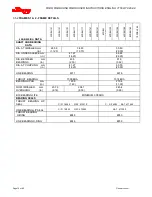
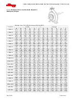
Suction 

Discharge 

16FRBH244 

8200 

4200 

6100 

11570 

9650 

7560 

7320 

3660 

5420 

8450 

6670 

10230 


(6050) 

(3100) 

(4500) 

(2600) 

(2170)  (1700) 

(5400) 

(2700) 

(4000) 

(1900) 

(1500)  (2300) 

18FRBH274 

8200 

4200 

6100 

11570 

9650 

7560 

8200 

4200 

6100 

9610 

7560 

11570 


(6050) 

(3100) 

(4500) 

(2600) 

(2170)  (1700) 

(6050) 

(3100) 

(4500) 

(2160) 

(1700)  (2600) 

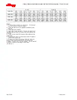
20FRBH304 

9080 

4750 

6780 

12900 

10720 

8450 

9080 

4750 

6780 

10760 

8450 

12900 


(6700) 

(3500) 

(5000) 

(2900) 

(2410)  (1900) 

(6700) 

(3500) 

(5000) 

(2420) 

(1900)  (2900) 

24FRBH304 

10850 

5830 

8130 

15480 

13120 

10230 

10850 

5830 

8130 

13080 

10230 

15660 


(8000) 

(4300) 

(6000) 

(3480) 

(2950)  (2300) 

(8000) 

(4300) 

(6000) 

(2940) 

(2300)  (3520) 


Notes: 

1)  F = External force (tension or compression)       M = External 

moment, clockwise or counter-clockwise 

2)  Forces and moments may be applied simultaneously in any 

direction 

3)  Values apply to all materials 
4)  Higher loads may be applicable, if direction and magnitude of 
individual loads are known, but these need written approval from 
Flowserve  
5)  Pumps must be on rigid foundations and baseplates must be 
fully grouted 
6)  Pump/baseplate should not used as pipe anchor.  Expansion 

joints must be properly tied 

7)  The pump mounting bolt torques specified must be used to 
prevent relative movement between the pump casing and 
baseplate.  (See section 6.6, 

Fastener torques.

)   The bolt material 

must have a minimum yield strength of 600 N/mm

2


(87 000 lb/in.

2

)

Содержание FRBH

Страница 1: ...BH FRBHX FRBHS Installation Operation Maintenance CENTRIFUGAL PAPER STOCK AND PROCESS PUMPS PCN 71569178 20 08 Original Instructions These instructions must be read prior to installing operating using and maintaining this equipment ...

Страница 2: ...TART UP OPERATION AND SHUTDOWN 33 5 1 Lubrication Methods 33 5 2 Pump lubricants 34 5 3 Direction of rotation 35 5 4 Guarding 35 5 5 Priming and auxiliary supplies 35 5 6 Starting the pump 36 5 7 Running the pump 36 5 8 Stopping and shutdown 37 5 9 Hydraulic mechanical and electrical duty 37 6 MAINTENANCE 38 6 1 General 38 6 2 Maintenance schedule 38 6 3 Spare parts 41 6 4 Recommended spares and c...

Страница 3: ...medies 42 General assembly drawings see 8 45 Grouting 4 4 21 Guarding 5 4 29 Handling 2 2 9 Hydraulic mechanical and electrical duty 5 9 31 Lifting 2 3 11 Location 4 1 21 Lubrication schedule see 5 2 Pump lubricants 28 Maintenance schedule 6 2 32 Piping 4 7 24 Priming and auxiliary supplies 5 5 29 Reassembly see 6 10 Assembly 36 Replacement parts see 6 3 and 6 4 34 Safety electrical see 4 9 26 Saf...

Страница 4: ...ly Explosive Atmospheres ATEX Where applicable the Directives and any additional Approvals cover important safety aspects relating to machinery and equipment and the satisfactory provision of technical documents and safety instructions Where applicable this document incorporates information relevant to these Directives and Approvals To confirm the Approvals applying and if the product is CE marked...

Страница 5: ... the work involved If the personnel in question do not already possess the necessary knowledge and skill appropriate training and instruction must be provided If required the operator may commission the manufacturer supplier to provide applicable training Always coordinate repair activity with operations and health and safety personnel and follow all plant safety requirements and applicable safety...

Страница 6: ... cause damage to the seal DO NOT RUN THE PUMP AT ABNORMALLY HIGH OR LOW FLOW RATES Operating at a flow rate higher than normal or at a flow rate with no back pressure on the pump may overload the motor and cause cavitation Low flow rates may cause a reduction in pump bearing life overheating of the pump instability and cavitation vibration 1 6 4 Products used in potentially explosive atmospheres M...

Страница 7: ...en into account in the temperatures stated The operator is responsible to ensure that the specified maximum liquid temperature is not exceeded Temperature classification T4 T1 is used when the liquid temperature varies and when the pump is required to be used in differently classified potentially explosive atmospheres In this case the user is responsible for ensuring that the pump surface temperat...

Страница 8: ...to have the correct corrosion resistance Avoid entrapment of liquid in the pump and associated piping due to closing of suction and discharge valves which could cause dangerous excessive pressures to occur if there is heat input to the liquid This can occur if the pump is stationary or running Bursting of liquid containing parts due to freezing must be avoided by draining or protecting the pump an...

Страница 9: ...NG QF 440 R01 2124841 Oil lubricated units only MECHANICAL SEAL FITTED DO NOT ADJUST PUMP CLEARANCE WITHOUT REFERENCE TO MANUFACTURER S INSTRUCTION MANUAL BEFORE STARTING THE PUMP ON SERVICE CHECK TO ENSURE CORRECT ROTATION OF MOTOR FAILURE TO DO THIS COULD RESULT IN SERIOUS DAMAGE TO THE EQUIPMENT BEFORE GROUTING REALIGN THIS UNIT RECHECK ALIGNMENT BEFORE STARTING FAILURE TO DO THIS COULD RESULT ...

Страница 10: ...levels at 1 m 3 3 ft from the directly driven pump for free field over a reflecting plane For estimating LwA sound power level re 1 pW add 14dBA to the sound pressure value If a pump unit only has been purchased for fitting with your own driver then the pump only noise levels from the table should be combined with the level for the driver obtained from the supplier If the motor is driven by an inv...

Страница 11: ...s or cartons may be unloaded using fork lift vehicles or slings dependent on their size and construction The pump should be lifted with suitably sized and located slings Do not use the shaft for lifting and take special care to prevent the pump from rotating in the slings due to unbalanced weight distribution 2 3 Lifting A crane must be used for all pump sets or components in excess of 25 kg 55 lb...

Страница 12: ...l number and a record kept of their location Pumps covered with plastic should not be stored in a cool environment because resulting condensation can cause rusting 2 5 Recycling and end of product life At the end of the service life of the product or its parts the relevant materials and parts should be recycled or disposed of using an environmentally acceptable method and in accordance with local ...

Страница 13: ...where the pump shaft is horizontal 3 3 5 Bearing housing For oil lubricated bearings a bulls eye level gauge is supplied Constant level oilers can also be fitted Two grease nipples enable grease lubricated bearings to be replenished between major service intervals 3 3 6 Stuffing box housing The stuffing box housing has a spigot rabbet fit between the pump casing and bearing housing for optimum con...

Страница 14: ... be plotted in torque units e g Nm instead of percentage torque to avoid confusion 3 4 3 MAXIMUM WORKING PRESSURES bar psi Above ambient temperature these maximum pressures shall be de rated Do no conduct a hydro on the complete pump set without the specific approval of Flowserve While the duty requirement will have been covered auxiliary items flange drillings and suction pressure limits may impo...

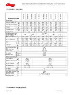
Страница 15: ...MAX SPHERE DIA mm in 12 7 5 17 8 7 25 4 1 0 30 5 1 2 43 2 1 7 25 4 1 0 35 6 1 4 38 1 1 5 55 9 2 2 19 1 75 27 9 1 1 55 9 2 2 68 6 2 7 WK2 kg x m2 lb x ft2 07 1 7 08 1 9 07 1 6 08 1 9 12 2 8 19 4 6 27 6 5 34 8 2 48 11 5 51 12 0 53 12 5 88 20 8 1 19 28 2 PUMP WEIGHT kg lb 195 430 202 445 202 445 227 500 302 665 231 510 270 595 513 1130 617 1360 476 1050 522 1150 739 1630 912 2010 MAX BACK PULLOUT WT ...

Страница 16: ...0 2 000 DIA UNDER SLEEVE mm in 41 27 1 625 66 68 2 625 DIA BETWEEN mm BEARINGS in 63 5 2 50 91 9 3 62 DIA AT COUPLING mm in 41 27 1 625 63 50 2 500 LINE BEARING 6311 6316 THRUST BEARING 7309 BUA 7314 BUA BEARING SPAN mm in 193 8 7 63 279 4 11 00 NOM IMPELLER mm OVERHANG in 207 8 8 18 204 7 8 06 245 4 9 66 B10 BEARING LIFE MINIMUM 3 YEARS BEARING SEALS THRUST BEARING LIP SEAL C R 16246 NAT 473010 C...

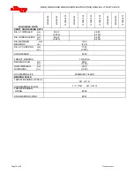
Страница 17: ...2 in 2 200 31 0 359 55 6 426 66 0 292 45 2 755 117 839 130 1090 169 352 54 4 564 87 4 1510 234 MAX SPHERE DIA mm in 27 9 1 1 55 9 2 2 68 6 2 7 48 3 1 9 96 5 3 8 40 6 1 6 40 6 1 6 50 8 2 0 61 2 4 61 2 4 WK2 kg x m2 lb x ft2 0 57 13 6 1 01 23 9 1 32 31 3 83 19 8 93 22 0 1 57 37 2 1 39 33 0 1 64 38 8 1 88 44 5 3 91 92 9 PUMP WT kg lb 602 1328 820 1808 992 2188 644 1420 816 1800 903 1990 1021 2250 848...

Страница 18: ...ER mm in 50 80 2 000 69 85 2 750 DIA UNDER SLEEVE mm in 66 68 2 625 82 55 3 250 DIA BETWEEN mm BEARINGS in 114 3 4 50 DIA AT COUPLING mm in 73 03 2 875 LINE BEARING 6320 THRUST BEARING 7318 BUA BEARING SPAN mm in 293 4 11 55 NOM IMPELLER mm OVERHANG in 312 2 12 29 B10 BEARING LIFE MINIMUM 3 YEARS BEARING SEALS THRUST BEARING LIP SEAL NAT 417191 LINE BEARING LIP SEAL C R 37389 NAT 415379 THRUST BEA...

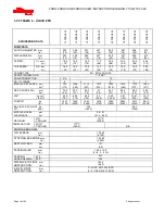
Страница 19: ...LER EYE AREA cm2 in 2 742 115 1258 195 2110 327 1510 234 1800 279 1419 220 1774 275 1400 217 MAX SPHERE DIA mm in 76 2 3 0 53 3 2 1 48 3 1 9 61 2 4 53 3 2 1 68 6 2 7 58 4 2 3 65 8 2 6 WK2 kg x m2 lb x ft2 3 29 78 1 4 89 116 4 96 118 4 0 95 0 5 05 120 0 5 91 140 16 81 399 19 13 454 PUMP WT kg lb 1247 2750 1565 3450 1653 3645 1429 3150 1669 3680 2023 4460 2517 5550 2812 6200 MAX BACK PULLOUT kg WT l...

Страница 20: ...2 08 3 625 DIA UNDER SLEEVE mm in 107 95 4 250 DIA BETWEEN mm BEARINGS in 127 0 5 00 146 1 5 75 DIA AT COUPLING mm in 98 43 3 875 LINE BEARING 22222C 22226C THRUST BEARING 7322 BUA BEARING SPAN mm in 279 0 11 00 538 5 21 20 NOM IMPELLER mm OVERHANG in 347 0 13 66 B10 BEARING LIFE MINIMUM 3 YEARS BEARING SEALS THRUST BEARING LIP SEAL NAT 417511 LINE BEARING LIP SEAL C R 37389 NAT 415379 C R 42419 N...

Страница 21: ...90 CD4MCUN ASTM A743 CF8M ASTM A890 CD4MCUN ASTM A890 CD4MCUN ASTM A743 CG3M ASTM A743 CN7M SHAFT SLEEVE ASTM A743 CG3M ASTM A743 CG3M ASTM A743 CG3M ASTM A890 CD4MCUN ASTM A743 CG8M ASTM A743 CN7M SHAFT AISI 1045 AISI 1045 AISI 1045 AISI 1045 AISI 1045 AISI 316 GLAND HALVES ASTM A890 CD4MCUN ASTM A743 CF8M ASTM A890 CD4MCUN ASTM A890 CD4MCUN ASTM A743 CN7M ASTM A743 CN7M PIPE PLUGS LIQUID END C I...

Страница 22: ... retention Since baseplate levelling is performed after the foundation has cured it is best to use extra long bolts that can be shortened after the installation is complete 4 4 Baseplate installation 4 4 1 Grouted baseplates Position the baseplate and pump next to the foundation and clean the foundation surface thoroughly Remove the rag packing from the pipe sleeves and place wedges or ships as cl...

Страница 23: ...orizontal alignment g Grout the baseplate A non shrinking grout should be used Make sure that the grout fills the area under the baseplate After the grout has cured check for voids and repair them Jackscrews shims and wedges should be removed from under the baseplate at this time If they were to be left in place they could rust swell and cause distortion in the baseplate h Run piping to the suctio...

Страница 24: ...angement drawing The spring will be compressed when loaded but some levelling adjustment of item E will be required 4 4 2 10 Position equipment pump base assembly over isolators and lower onto the adjusting nut washer C 4 4 2 11 Reassemble jam nut B but do not tighten 4 4 2 12 Install motor in approximate position in order to have springs compressed in near to final state 4 4 2 13 The spring is we...

Страница 25: ...er coupling gap is verified As indicated the gap may be adjusted to ensure adequate axial bolt clearance g The parallel and angular vertical alignment is made by shimming under the motor h The pump and motor shafts are then aligned horizontally both parallel and angular by moving the pump to the fixed motor The pump feet are tightened down i Both horizontal and vertical alignment is again final ch...

Страница 26: ...on Rotate the pump shaft and record the dial reading at the top bottom and each side Correct the parallel alignment by adding or removing shims under the driver and or moving the driver horizontally Repeat this procedure until the maximum total indicator reading T I R is within 0 08 mm 0 003 inch 4 5 4 Angular Alignment Mount the magnetic base mounted on the pump half coupling hub either face or O...

Страница 27: ...e rust nicks or burrs Install the correct size sheave on the pump shaft and locate the sheave axially to minimize overhang Re check the impeller axial clearance and ensure that the pump is properly secured to the baseplate Install the driver on the adjustable base provided and install the driver sheave in line with the pump sheave Ensure that the sheaves are tight on the shafts With a dial indicat...

Страница 28: ... losses and hydraulic noise in the pipework it is good practice to choose pipework that is one or two sizes larger than the pump suction and discharge Typically main pipework velocities should not exceed 2 m s 6 ft sec suction and 3 m s 9 ft sec on the discharge Take into account the available NPSH that must be higher than the required NPSH of the pump Never use the pump as a support for piping Ma...

Страница 29: ...00 870 1300 700 560 460 700 350 530 240 200 300 4FRBH182 3 3530 1760 2580 4890 3780 3110 1330 680 1000 1420 1160 1780 2600 1300 1900 1100 850 700 980 500 740 320 260 400 8FRBH182 3 5020 2440 3800 6670 5340 4450 3530 1760 2580 3780 3110 4890 3700 1800 2800 1500 1200 1000 2600 1300 1900 850 700 1100 10FRBH182 3 6100 2980 4610 8000 6670 5340 5020 2440 3800 5340 4450 6670 4500 2200 3400 1800 1500 1200...

Страница 30: ...0 4300 6000 3480 2950 2300 8000 4300 6000 2940 2300 3520 Notes 1 F External force tension or compression M External moment clockwise or counter clockwise 2 Forces and moments may be applied simultaneously in any direction 3 Values apply to all materials 4 Higher loads may be applicable if direction and magnitude of individual loads are known but these need written approval from Flowserve 5 Pumps m...

Страница 31: ...o feed the gland packing with liquid to provide lubrication and prevent the ingress of air This is normally achieved with a supply from the pump discharge volute to the stuffing box A control valve is fitted in the line to enable the pressure to the gland to be controlled If the pumped liquid is dirty and cannot be used for sealing a separate clean compatible liquid supply to the gland at 1 bar 15...

Страница 32: ...mpatibility when wiring up and installing equipment on site Attention must be paid to ensure that the techniques used during wiring installation do not increase electromagnetic emissions or decrease the electromagnetic immunity of the equipment wiring or any connected devices If in any doubt contact Flowserve for advice 4 9 4 The motor must be wired up in accordance with the motor manufacturer s i...

Страница 33: ...Capacities 5 1 3 Grease Lubrication Grease lubricated pumps and electric motors are supplied pre greased 5 1 4 Oil Mist Lubrication FRBH pumps may be lubricated by pure or purge oil mist See comments below 5 1 4 1 Purge Mist In the case of purge mist an oil level is maintained in the bearing frame No changes are required to be made to the pump however the oil level must be maintained at site glass...

Страница 34: ...l DTE25 Q8 Q8 Verdi 32 Q8 Haydn 32 Q8 Verdi 68 Q8 Haydn 68 Q8 Verdi 46 Q8 Haydn 46 Shell Shell Tellus 32 Shell Tellus 37 Shell Tellus 01 C 68 Shell Tellus 01 68 Shell Tellus 01 C 46 Shell Tellus 01 46 Texaco Rando Oil HD 32 Rando Oil HD AZ 32 Rando Oil 68 Rando Oil HD C 68 Rando Oil 46 Rando Oil HD B 46 Wintershall BASF Group Wiolan HN32 Wiolan HS32 Wiolan HN68 Wiolan HS68 Wiolan HN46 Wiolan HS46 ...

Страница 35: ...requency of lubrication Lubricant and bearing temperature analysis can be useful in optimising lubricant change intervals The bearing temperature may be allowed to rise to 55 ºC 131 ºF above ambient but should not exceed 95 C 204 F For most operating conditions a quality grease having a lithium soap base and NLGI consistency of No 2 or No 3 is recommended The drop point should exceed 175 ºC 350 ºF...

Страница 36: ... re started check to ensure leakage is taking place at the packed gland If hot liquids are being pumped it may be necessary to slacken the gland nuts to achieve leakage The pump should be run for 30 minutes with steady leakage and the gland nuts tightened by 10 degrees at a time until leakage is reduced to an acceptable level normally a minimum of 120 drops per minute is required Bedding in of the...

Страница 37: ...derstood that during the life of the product these may change The following notes may help the user decide how to evaluate the implications of any change If in doubt contact your nearest Flowserve office 5 9 1 Specific gravity SG Pump capacity and total head in metres feet do not change with SG however pressure displayed on a pressure gauge is directly proportional to SG Power absorbed is also dir...

Страница 38: ...r or compressed inert gas to clean clothes Before working on the pump take measures to prevent an uncontrolled start Put a warning board on the starting device with the words Machine under repair do not start With electric drive equipment lock the main switch open and withdraw any fuses Put a warning board on the fuse box or main switch with the words Machine under repair do not connect Never clea...

Страница 39: ...ng are contained in the table below Please note that standard pumps are oil lubricated Grease only when factory installed grease fittings are supplied Table 6 2 3 1 Bearing Regreasing Quantities BRG THRUST BEARING LINE BEARING FRAME SIZE OZ CU IN CU CM OZ CU IN CU CM 1 1 1 2 20 2 2 4 40 2 3 3 6 60 4 4 9 80 3 7 8 5 140 5 6 1 100 4 9 11 0 180 6 7 3 120 Regrease via grease nipples every 2 000 hours o...

Страница 40: ...lass window Refer to section 5 1 1 for methods of oil fill section 5 2 1 for oil grade recommendations and 5 2 4 for the schedule and temperature limits 6 2 4 Mechanical seals No adjustment is possible When leakage reaches an unacceptable level the seal will need replacement 6 2 5 Gland packing 6 2 5 1 Water Lubricated Packing The stuffing box split gland can be completely removed for re packing o...

Страница 41: ... 1 set of bearings line and thrust 2 sets of gland packing 2 shaft sleeves 2 sets of gaskets and seals 2 lantern rings 2 casing wear rings 1 impeller optional 2 mechanical seals 1 wearplate 6 5 Tools required A typical range of tools that will be required to maintain these pumps is listed below Readily available in standard tool kits and dependent on pump size Open ended spanners wrenches to suit ...

Страница 42: ...etween the impeller and stuffing box head j Remove the bolts connecting the rear support foot 3134 to the baseplate k Remove the frame to casing bolts l Withdraw the rotating element from the casing For FRBHS designs there is a loose adapter 1340 that spaces the bearing bracket 3130 from the pump casing 1110 This item may stay lodged within the casing or could be removed with the rotating element ...

Страница 43: ...if fitted a Replace sleeve if grooved pitted or worn b Clean the shaft and inspect for evidence of corrosion evidence of cracking fatigue or mechanical damage Remove all burrs or nicks paying particular attention to the areas under the lip seals Check that the shaft is straight within 0 002 inch 0 050 mm 6 9 3 Gaskets and O rings After dismantling discard and replace 6 9 4 Bearings a It is recomme...

Страница 44: ... of the seal on the shaft h Using capscrews and lockwashers attach the thrust bearing clamping ring 2542 to the thrust bearing housing 3230 Lock the threads using Loctite 242 or equivalent The thrust bearing clamping ring 2542 is provided with one extra hole midway between two adjacent bolt holes to permit free oil flow On oil lubricated units this hole must align with the cast oil return at the b...

Страница 45: ...100 over the shaft sleeve 2445 and orientate the lantern ring connections to auxiliary piping Refer to Figure 6 These connections are normally placed on the vertical centerline for proper venting and draining as well as providing optimum gland stud access b Push the stuffing box head 4100 back against the bearing frame flange face Back off the thrust bearing housing jacket screws and tighten the t...

Страница 46: ...so caution must be exercised when moving around the casing 6 10 9 All pumps except FRBHS a Smear anti seize compound on the pump casing 1110 and stuffing box head 4100 rabbit fit spigot diameters to ease assembly and future disassembly 6 10 10 Rotor unit a With a sling around the bearing frame placed so as to balance the weight lift the frame impeller assembly keeping the shaft horizontal b Instal...

Страница 47: ... procedure with the exception that Loctite 242 is applied to the impeller nut 2912 threads Torque the nut in accordance with information below MINIMUM IMPELLER NUT TIGHTENING TORQUE FRAME Ft lbs Nm 1 100 140 2 300 400 3 300 400 4 550 750 e Assemble the mechanical seal gland plate and gasket and fasten using gland studs 6573 Secure with nuts 6580 and tighten each by hand Further tighten the nuts in...

Страница 48: ...ing flange and bearing frame end face Determine the required impeller axial running clearance from Section I and add this to the above measurement to establish the required gap setting 6 11 1 3 a Loosen the thrust bearing housing hold down capscrews slightly and tighten the jack screws Until the required dial indicator reading 6 11 1 1 or housing gap reading 6 11 1 2 is achieved b Alternately and ...

Страница 49: ...pipes and system Air or vapour pocket in suction line Check suction line design for vapour pockets Air leaks into suction line Check suction pipe is airtight Air leaks into pump through mechanical seal sleeve joints casing joint or pipe plugs Check and replace faulty parts CONSULT FLOWSERVE Foot valve too small Investigate replacing the foot valve Foot valve partially clogged Clean foot valve Inle...

Страница 50: ...oint failure Replace joint and check for damage Shaft sleeve worn or scored or running off centre Check and renew defective parts Mechanical seal improperly installed Check alignment of faces or damaged parts and assembly method used Incorrect type of mechanical seal for operating conditions CONSULT FLOWSERVE Shaft running off centre because of worn bearings or misalignment Check misalignment and ...

Страница 51: ...v er liquid PROBABLE CAUSES POSSIBLE REMEDIES Improper installation of bearings damage during assembly incorrect assembly wrong type of bearing etc Check method of assembly possible damage or state of cleanliness during assembly and type of bearing used Remedy or CONSULT FLOWSERVE if necessary Damaged bearings due to contamination Check contamination source and replace damaged bearings C MOTOR ELE...

Страница 52: ...hrust bearing 3130 Bearing Bracket 3134 Support foot 3230 Thrust brg Hsg 3260 Bearing cover 3712 Bearing lock nut 3856 Oil site gauge 4100 Stuffing box 4110 Expeller Housing 4121 Gland split 4130 Packing 4132 Neck bush 4134 Lantern Ring 4300 1 Radial lip seal 4300 2 Radial lip seal 4590 1 Gasket wearplate 4590 2 Gasket sleeve 4590 3 Gasket Casing 4590 4 Gasket Impeller 4610 1 O ring imp nut 4610 2...

Страница 53: ... Page 53 of 60 Flowserve com 8 2 FRBH FRBHX FRBHS Frames 1 3 and 4A Exploded view 2540 3260 3130 4610 1 4610 1 3856 6700 6710 2110 3230 4300 2 3712 6542 3031 3011 2542 6578 4300 3260 6578 3130 4610 3856 3134 6700 2110 3011 2542 3031 6541 3712 6700 4610 3230 4300 ...

Страница 54: ...O ring thrust brg 2200 Impeller 4100 Stuffing Box 4610 3 O ring Line brg 2250 Radial Impeller 4110 Expeller Housing 4610 4 O ring Stuffing Box 2445 Shaft sleeve 4121 Gland split 4610 5 O ring Expeller Hsg 2540 Deflector 4130 Packing 6541 Lockwasher 2542 Clamping ring 4132 Neck bush 6572 Stud wear plate 2912 Impeller Nut 4134 Lantern Ring 6580 Nut wear plate 3011 Radial ball bearing 4300 1 Radial l...

Страница 55: ...wserve com 2540 4300 1 4300 2 3260 1340 3130 6578 3856 3011 2542 3031 6542 3712 3230 4610 1 4610 2 6700 2110 6710 2540 4300 3260 4610 1340 3130 6578 3856 6700 2110 4610 6700 4300 3230 3134 3712 6541 3031 2542 3011 8 4 FRBH FRBHX FRBHS Frame assembly B4B 2 piece Frame Exploded View ...

Страница 56: ...of 60 Flowserve com 8 5 FRBH Frames 1 4 liquid end Exploded View Where the Expeller is utilized see 8 4 1 for the parts list and exploded view 1110 1915 2912 4610 2200 4590 4100 4590 4132 2445 4121 4130 1110 1915 2912 4610 2200 4590 4100 4590 4132 2445 4134 4121 3130 4130 ...

Страница 57: ...TIONS ENGLISH 71569178 20 08 Page 57 of 60 Flowserve com 8 6 FRBHX Exploded view 1110 1915 2912 4610 1 2200 4590 4121 2445 4590 4100 4130 4610 2 2250 1110 1915 2912 4610 2200 4590 4110 4590 2250 4610 4100 4590 2445 4134 4121 4130 3130 ...

Страница 58: ...e gauge 4610 3 O ring Line brg 2200 Impeller 4100 Stuffing box 6541 Lockwasher 2445 Shaft sleeve 4121 Gland split 6572 Stud wear plate 2540 Deflector 4130 Packing 6580 Nut wear plate 2542 Clamping ring 4132 Neck bush 6700 1 Key coupling 2912 Impeller Nut 4134 Lantern Ring 6700 2 Key impeller 3011 Radial ball bearing 4300 1 Radial lip seal Line brg 3031 Thrust bearing 4300 2 Radial lip seal Thrust ...

Страница 59: ...or inclusion into User Instructions such as for a driver instrumentation controller sub driver seals sealant system mounting component etc are included under this section If further copies of these are required they should be obtained from the purchaser for retention with these User Instructions Where any pre printed set of User Instructions are used and satisfactory quality can be maintained only...

Страница 60: ... 4497 Asia Pacific Flowserve Pte Ltd 10 Tuas Loop Singapore 637345 Telephone 65 6771 0600 Fax 65 6862 2329 Visit our web site at www flowserve com Your Flowserve factory contact Flowserve Pump Division 5310 Taneytown Pike Taneytown Maryland USA 21787 Telephone 1 410 756 2602 Fax 1 410 756 2615 In Canada Flowserve Pump Division PO Box 40 15 Worthington Drive Brantford On N3T5M5 Telephone 1 519 753 ...

Отзывы: