background image

FP USER INSTRUCTIONS ENGLISH 71576286 - 07/06

Page 5 of 35

1.6 Safety

1.6.1 Summary of safety markings

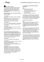
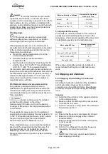
These User Instructions contain specific safety
markings where non-observance of an instruction
would cause hazards. The specific safety markings
are:

This symbol indicates electrical safety

instructions where non-compliance will involve a
high risk to personal safety or the loss of life.

This symbol indicates safety instructions where

non-compliance would affect personal safety and
could result in loss of life.

This symbol indicates “hazardous substances

and toxic fluid” safety instructions where non-
compliance would affect personal safety and could
result in loss of life.

This symbol indicates safety

instructions where non-compliance will involve some
risk to safe operation and personal safety and would
damage the equipment or property.

This symbol indicates explosive atmosphere

zone marking according to ATEX. It is used in safety
instructions where non-compliance in the hazardous
area would cause the risk of an explosion.

This symbol is used in safety instructions to

remind not to rub non-metallic surfaces with a dry
cloth; ensure cloth is damp. It is used where non-
compliance in the hazardous area would cause the
risk of an explosion.

This sign is not a safety symbol but indicates

an important instruction in the assembly process.

1.6.2 Personnel qualification and training

All personnel involved in the operation, installation,
inspection and maintenance of the unit must be
qualified to carry out the work involved. If the
personnel in question do not already possess the
necessary knowledge and skill, appropriate training
and instruction must be provided. If required the
operator may commission the manufacturer/supplier
to provide applicable training.

Always coordinate repair activity with operations and
health and safety personnel, and follow all plant
safety requirements and applicable safety and health
laws and regulations.

1.6.3 Safety action

This is a summary of conditions and actions to
prevent injury to personnel and damage to the
environment and to equipment. For products
used in potentially explosive atmospheres
section 1.6.4 also applies.

NEVER DO MAINTENANCE WORK

WHEN THE UNIT IS CONNECTED TO POWER

GUARDS MUST NOT BE REMOVED WHILE

THE PUMP IS OPERATIONAL

DRAIN THE PUMP AND ISOLATE

PIPEWORK BEFORE DISMANTLING THE PUMP
The appropriate safety precautions should be taken
where the pumped liquids are hazardous.

FLUORO-ELASTOMERS (When fitted.)

When a pump has experienced temperatures over
250 ºC (482 ºF), partial decomposition of fluoro-
elastomers (example: Viton) will occur. In this
condition these are extremely dangerous and skin
contact must be avoided.

HANDLING COMPONENTS

Many precision parts have sharp corners and the
wearing of appropriate safety gloves and equipment
is required when handling these components. To lift
heavy pieces above 25 kg (55 lb) use a crane
appropriate for the mass and in accordance with
current local regulations.

THERMAL SHOCK

Rapid changes in the temperature of the liquid within
the pump can cause thermal shock, which can result
in damage or breakage of components and should
be avoided.

NEVER APPLY HEAT TO REMOVE

IMPELLER
Trapped lubricant or vapour could cause an
explosion.

HOT (and cold) PARTS

If hot or freezing components or auxiliary heating
supplies can present a danger to operators and
persons entering the immediate area action must be
taken to avoid accidental contact. If complete
protection is not possible, the machine access must
be limited to maintenance staff only, with clear visual
warnings and indicators to those entering the
immediate area. Note: bearing housings must not be
insulated and drive motors and bearings may be hot.

If the temperature is greater than 68 °C (175 °F)
or below 5 °C (20 °F) in a restricted zone, or
exceeds local regulations, action as above shall
be taken.

Содержание Flowserve 71576286

Страница 1: ...USER INSTRUCTIONS FP centrifugal pump Multi stage single suction and radial joint plan pump type centrifugal pump PCN 71576286 07 06 E Installation Operation Maintenance ...

Страница 2: ...s 16 4 7 Final shaft alignment check 17 4 8 Protection systems 17 5 COMMISSIONING START UP OPERATION AND SHUTDOWN 17 5 1 Direction of rotation 17 5 2 Guarding 17 5 3 Priming and auxiliary supplies 18 5 4 Starting the pump 18 5 5 Running the pump 19 5 6 Stopping and shutdown 20 5 7 Hydraulic mechanical and electrical duty 21 5 8 Pumps for Food Use or Potable Water 21 PAGE 6 MAINTENANCE 21 6 1 Gener...

Страница 3: ...13 Internal coating 6 2 6 24 Lifting 2 3 11 Location 4 1 13 Maintenance 6 21 Maintenance schedule 6 2 22 Mechanical seal 6 2 4 23 Nomenclature 3 2 12 Nameplate 1 7 1 8 Operating limits see 3 1 12 Ordering spare parts 6 3 1 24 Parts lists 8 2 32 Piping 4 5 15 Protection systems 4 8 17 Pump masses 2 2 2 10 Receipt and unpacking 2 1 10 Recommended fill quantities see 6 2 1 23 Recommended grease lubri...

Страница 4: ...is document incorporates information relevant to these Directives and Approvals To confirm the Approvals applying and if the product is CE marked check the serial number plate markings and the Certification See section 9 Certification 1 3 Disclaimer Information in these User Instructions is believed to be reliable In spite of all the efforts of Flowserve Pump Division to provide sound and all nece...

Страница 5: ...alth and safety personnel and follow all plant safety requirements and applicable safety and health laws and regulations 1 6 3 Safety action This is a summary of conditions and actions to prevent injury to personnel and damage to the environment and to equipment For products used in potentially explosive atmospheres section 1 6 4 also applies NEVER DO MAINTENANCE WORK WHEN THE UNIT IS CONNECTED TO...

Страница 6: ...e higher than normal or at a flow rate with no backpressure on the pump may overload the motor and cause cavitations Low flow rates may cause a reduction in pump bearing life overheating of the pump instability and cavitations vibration 1 6 4 Products used in potentially explosive atmospheres Measures are required to Avoid excess temperature Prevent build up of explosive mixtures Prevent the gener...

Страница 7: ...he liquid temperature varies and the pump could be installed in different hazardous atmospheres In this case the user is responsible for ensuring that the pump surface temperature does not exceed that permitted in the particular hazardous atmosphere If an explosive atmosphere exists during the installation do not attempt to check the direction of rotation by starting the pump unfilled Even a short...

Страница 8: ...s Where there is the potential hazard of a loss of a seal barrier fluid or external flush the fluid must be monitored If leakage of liquid to atmosphere can result in a hazard the installation of a liquid detection device is recommended 1 6 4 7 Maintenance to avoid the hazard CORRECT MAINTENANCE IS REQUIRED TO AVOID POTENTIAL HAZARDS WHICH GIVE A RISK OF EXPLOSION The responsibility for compliance...

Страница 9: ...ng with your own driver then the pump only noise levels from the table should be combined with the level for the driver obtained from the supplier If the motor is driven by an inverter it may show an increase in noise level at some speeds Consult a Noise Specialist for this calculation For units driven by equipment other than electric motors or units contained within enclosures see the accompanyin...

Страница 10: ...parts or further accessories 2 2 Handling 2 2 1 General instructions concerning handling Boxes crates pallets or cartons may be unloaded using forklift vehicles or slings dependent on their size and construction See 2 3 1 for positioning of slings To lift heavy pieces above 25 kg 55 lb use a winch adapted to the mass and in accordance with the current local regulations To lift machines or pieces w...

Страница 11: ...ct or its parts the relevant materials and parts should be recycled or disposed of using an environmentally acceptable method and local regulations If the product contains substances which are harmful to the environment these should be removed and disposed of in accordance with current regulations This also includes the liquids and or gases in the seal system or other utilities Make sure that haza...

Страница 12: ...00 min 1 Maximum number of stages according to rotation speed 3500 min 1 2900 min 1 1750 min 1 1450 min 1 50 FP 6 7 7 7 65 FP 4 6 7 7 80 FP 3 5 6 6 100 FP 3 5 6 6 122 FP 4 5 125 FP 2 3 4 5 152 FP 202 FP 3 4 The maximum speed is shown on the pump nameplate 3 2 Nomenclature Characteristics shown on the nameplate fixed on the pump are as shown below Each pump is supplied with the following nameplate ...

Страница 13: ... NOT be distorted or pulled down onto the surface of the foundation but should be supported to maintain the original alignment Anchor bolts must be in accordance with the foot bolt holes Use anchor bolts of accepted standards and sufficient to ensure seave fitting in the foundation Particularly this applies to individual plates where the anchor bolts have to withstand the driving torque NF E 27 81...

Страница 14: ...ure and should be corrected to allow for thermal expansion at operating temperature In pump installations involving high liquid temperatures the unit should be run at the actual operating temperature shut down and the alignment checked immediately 4 4 2 Alignment methods Ensure pump and driver are isolated electrically and the half couplings are disconnected Ensure that the pump pipework suction a...

Страница 15: ...e pump Never use pump as a support for piping Do not mount expansion joints in such a way that their force due to internal pressure may act on the pump flange Maximum forces and moments allowed on the pump flanges vary with the pump size and type These external strains may cause misalignment hot bearings worn couplings vibrations and the possible failure of the pump casing When designing the pipes...

Страница 16: ... ensuring that there are no peaks c If a foot valve is necessary do not oversize it because it would generate pulsations valve beating Do not tighten flanges before the final check see 4 5 4 4 5 3 Discharge piping 4 5 3 1 Design of a discharge line a If discharge line is provided with a divergent its total angle will be between 7 and 12 b Install the discharge valve after the non return valve down...

Страница 17: ...owserve If there is any possibility of the system allowing the pump to run against a closed valve or below minimum continuous safe flow a protection device should be installed to ensure the temperature of the liquid does not rise to an unsafe level If there are any circumstances in which the system can allow the pump to run dry or start up empty a power monitor should be fitted to stop the pump or...

Страница 18: ...mp suction pump With foot valve a Fill suction pipe and casing with liquid from an independent source pressure 1 to 2 bars b Let air escape by removing the plugs situated on the flange of the discharge casing and suction casing for the 122 152 to 202 FP pumps For the 50 to 125 FP pumps plugs are located on pipes c When the pump is totally free of air bubbles replace the plugs Air escape Air escape...

Страница 19: ...is operation the operator must be very careful Safety gloves are compulsory and loose clothes are not allowed above all to the arms to avoid being caught by the pump shaft The pump should be run for ten minutes with steady leakage and the gland nuts tightened by 10 degrees at a time until leakage is reduced to an acceptable level The temperature of the gland should be checked after each round of t...

Страница 20: ... for the preferred operating flow region typically this may extend to 70 to 120 of the pump best efficiency point outside the preferred flow region the actual vibration experienced may be multiplied by up to 2 These standard values can vary with the rotational speed and the power absorbed by the pump For any special case do not hesitate to consult us Measuring vibration at regular intervals will t...

Страница 21: ... NPSHA NPSHR and that noise and vibration are within local requirements and regulations 5 7 4 Net positive suction head NPSHA NPSH available NPSHA is the head available at the impeller inlet above the vapour pressure of the pumped liquid NPSH required NPSHR is the minimum head required at the impeller inlet above the vapour pressure of the pumped liquid to avoid excessive cavitation and extreme pe...

Страница 22: ...nts 6 2 Maintenance schedule It is recommended that a maintenance plan and schedule is adopted in line with these User Instructions It should include the following a The pump must be completely vented and drained and rendered inert before any disassembly operation b Any auxiliary systems installed must be monitored if necessary to ensure they function correctly c During cleaning of the pump ensure...

Страница 23: ... pump unit the user must a Refer to the fault finding chart chapter 7 of this leaflet to apply the recommended solutions b Ensure that your equipment corresponds to the arrangements of this leaflet c Contact FLOWSERVE after sales Department if the problem persists 6 2 4 Mechanical seals The current maintenance is limited to seal control It is necessary to detect any small leakage which announces t...

Страница 24: ...st be inspected periodically Any wear or cracks of the coating found must be immediately repaired Failure to do this may lead to accelerated wear of the coating during operation and corrosion of the exposed base metal depending on the material and pumped liquid Special attention must be paid to the coating edges Any loss of coating material is considered to be normal wear and tear on the pump and ...

Страница 25: ...owserve replacement parts are available Refer to sectional drawings for part numbers and identification REPAIR OF THE PUMP If the pump presents abnormalities or a persistent malfunction contact immediately FLOWSERVE After sales Service Tel 02 43 40 57 57 33 2 43 40 57 57 Fax 02 43 40 58 17 33 2 43 40 58 17 According to the After sales Service instructions disassembly will be limited to the dismant...

Страница 26: ...arge pipes valves back pressure Worn wear ring surfaces Foresee pump mending CONSULT FLOWSERVE Seizure jamming CONSULT FLOWSERVE Excessive strains on flanges Check the flange connections and eliminate strains pipe positioning or elastic sleeves mounting Defective gland packing on the shaft Check and replace all the gland packing parts Mechanical seal CONSULT FLOWSERVE Defective motor bearings CONS...

Страница 27: ...FP USER INSTRUCTIONS ENGLISH 71576286 07 06 Page 27 of 35 8 PARTS LIST AND DRAWINGS 8 1 Sectional drawings 8 1 1 122 FP Pumps ...

Страница 28: ...FP USER INSTRUCTIONS ENGLISH 71576286 07 06 Page 28 of 35 8 1 2 152 FP Pumps ...

Страница 29: ...FP USER INSTRUCTIONS ENGLISH 71576286 07 06 Page 29 of 35 8 1 3 202 FP Pumps ...

Страница 30: ...FP USER INSTRUCTIONS ENGLISH 71576286 07 06 Page 30 of 35 8 1 4 50 FP Pumps ...

Страница 31: ...FP USER INSTRUCTIONS ENGLISH 71576286 07 06 Page 31 of 35 8 1 5 65 FP 80 FP 100 FP 125 FP Pumps ...

Страница 32: ...ng housing 6700 04 Key 3260 Bearing cover 6814 Grub screw 3853 Grease nipple 9331 Cover plate 8 2 2 Parts list pumps 152 FP N DESIGNATION N DESIGNATION 1130 Suction casing 4134 Lantern ring 1140 Discharge casing 4590 01 Gasket 1160 Stage casing 4590 02 Gasket 1410 01 Diffuser 4610 01 Round section joint ring 1410 02 Diffuser 4610 02 Round section joint ring 1500 01 Casing wear ring 4610 03 Round s...

Страница 33: ... housing 6581 01 Hexagon nut 3260 Bearing cover 6581 02 Hexagon nut 3853 Grease nipple 6700 01 Key 4110 Stuffing box housing 6700 02 Key 4120 Stuffing box gland 6700 03 Key 4130 Gland packing 6700 04 Key 4131 Follower 9331 Cover plate 8 2 4 Parts list pumps 50 FP N DESIGNATION N DESIGNATION 1130 Suction casing 3853 Grease nipple 1140 Discharge casing 4120 Gland 1150 Stage casing 4130 Gland packing...

Страница 34: ...ained with these User Instructions 9 CERTIFICATION Certificates determined from the Contract requirements are provided with these instructions where applicable Examples are certificates for CE marking ATEX marking etc If required copies of other certificates sent separately to the Purchaser should be obtained from the Purchaser for retention with these User Instructions 10 OTHER RELEVANT DOCUMENTA...

Страница 35: ...06 03 04 Pantech 21 Singapore 128388 Telephone 65 6775 3003 Fax 65 6779 4607 Local Flowserve factory representatives North America Flowserve 5310 Taneytown Pike PO Box 91 Taneytown MD 21787 0091 USA Telephone 1 410 756 2602 Customer Service FAX 1 410 756 2615 Parts inquiry Order PH 1 800 526 3569 South America Flowserve do Brasil Ltda Av Don Helder Camara 5451 20771 001 Rio de Janerio Tel 55 21 21...

Отзывы: